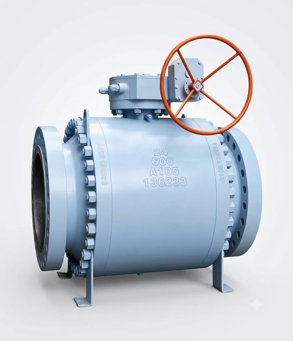
Product Overview
The HN106 Fixed Ball Valve is designed for on-off shut-off service in ANSI pipeline systems. The fixed ball structure supports the ball with trunnion-style bearing components, helping reduce operating torque and improve stability in larger sizes or higher pressure classes.
This valve series is suitable for oil, gas, water, steam and compatible industrial media where reliable quarter-turn isolation is required. Typical applications include petrochemical, refinery, power plant, pipeline and general industrial services.
HN106 can be supplied with raised face, butt-welded or ring type joint end configurations depending on pressure class and project requirements. The catalog reference covers Class 150, 300, 600, 900, 1500 and 2500 configurations, with fire-safe, anti-static, injection and gear/operator options available according to project specification.
Key Features
- Fixed ball structure for stable operation in ANSI pipeline shut-off service.
- Trunnion-style support and bearing components to help reduce operating torque.
- RF, butt-welded and RTJ end options depending on pressure class and project requirement.
- Fire-safe design reference according to API 607 or BS 6755.
- Anti-static device between ball, stem and body movement components.
- Blow-out resistant stem design for improved operating safety.
- Seat injection and sealing options for dirty service or maintenance support.
- Full bore or reduced bore options may be selected according to flow requirements.
- Handle, worm gear, electric, pneumatic or hydraulic operation may be selected according to size and torque requirements.
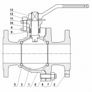
Sectional Structure and Materials
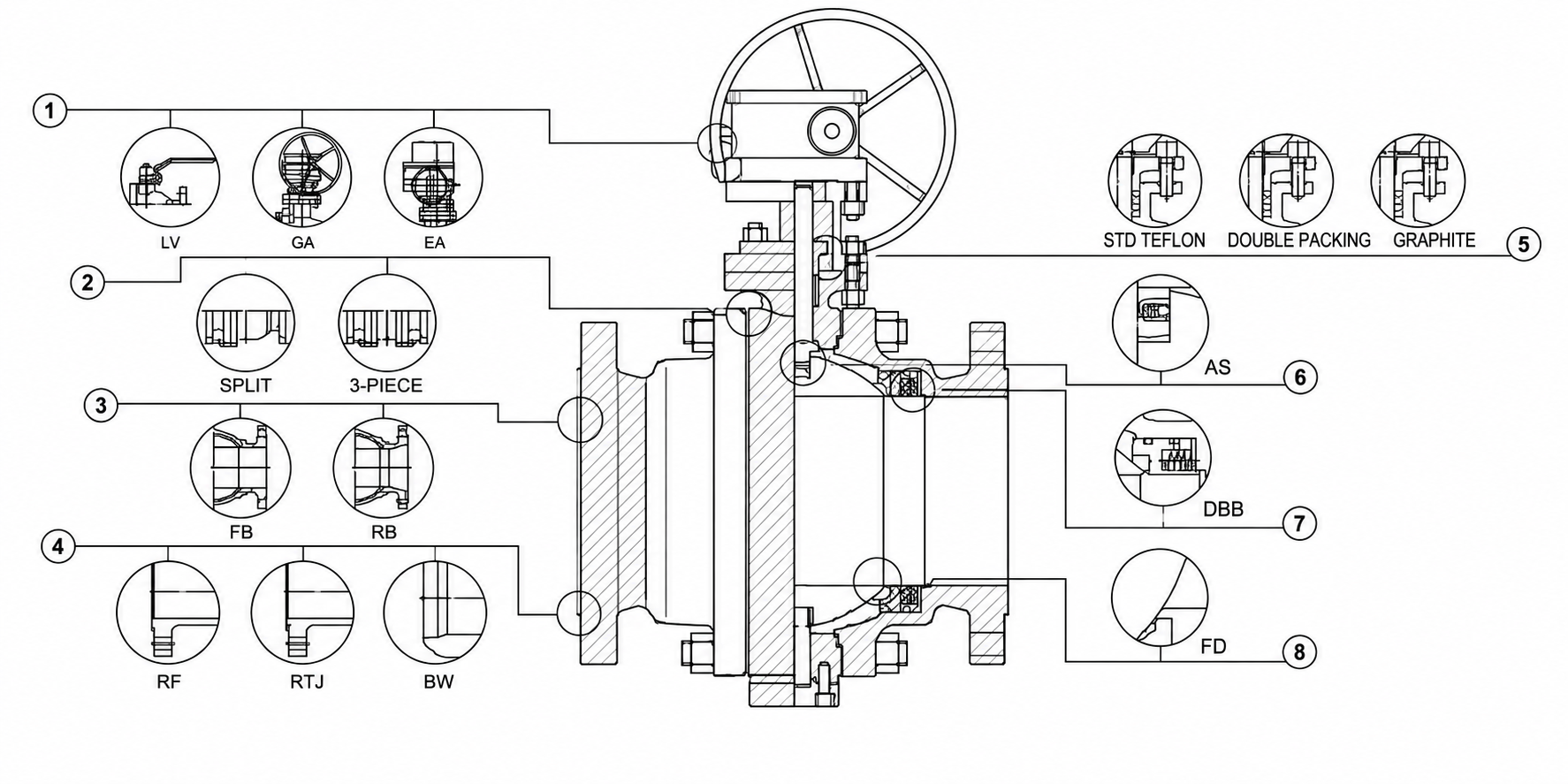
The numbered sectional drawing corresponds to the position numbers in the materials table. Final material selection should be confirmed according to pressure class, temperature, medium compatibility and project specification.
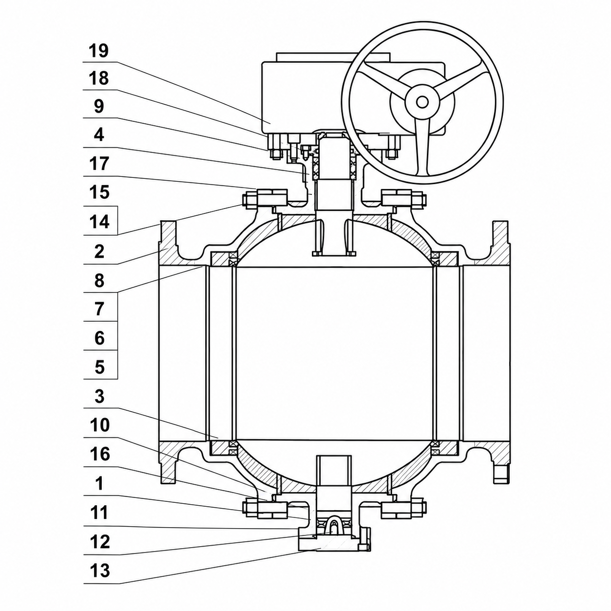
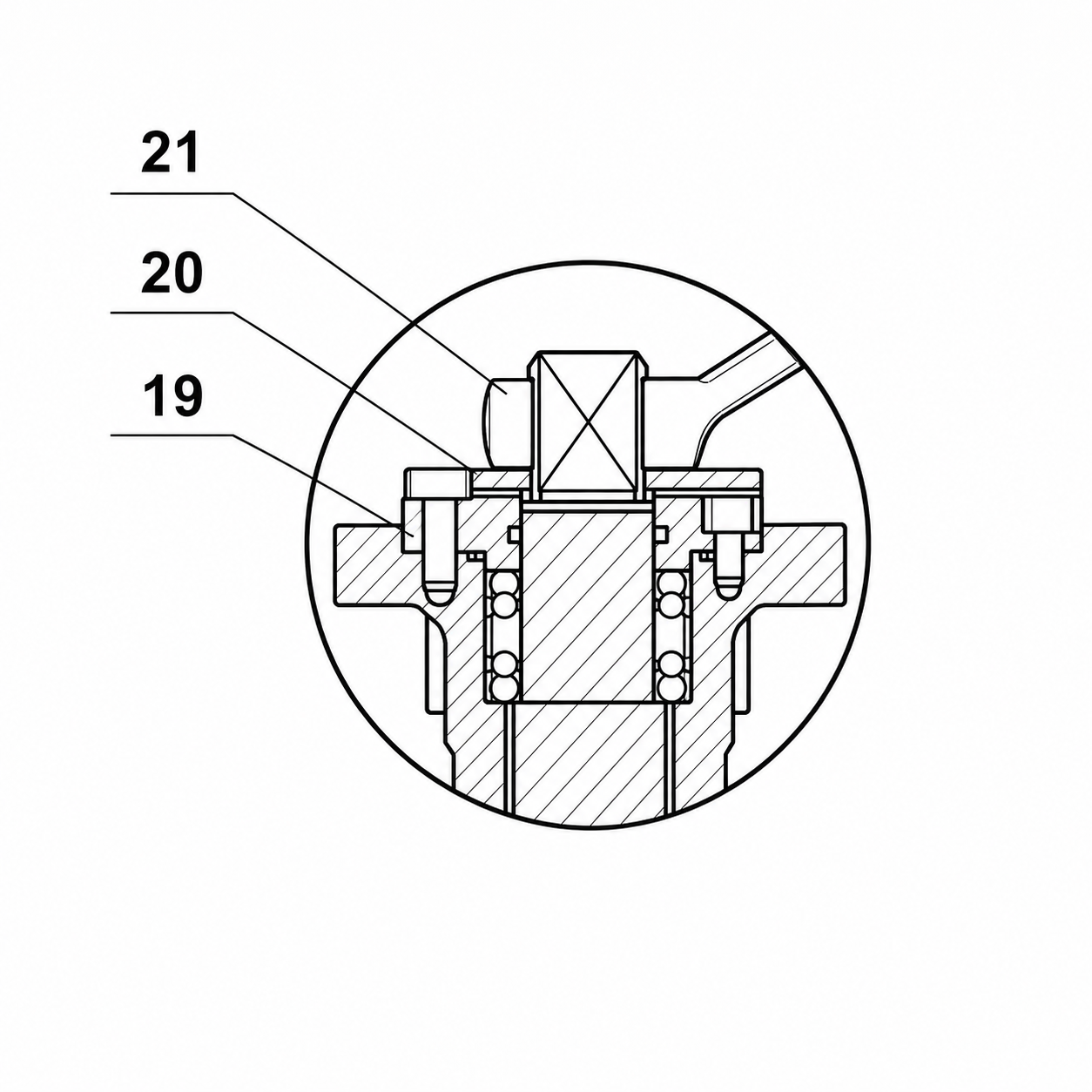
| Pos. | Parts Name | Carbon Steel | Stainless Steel | Low Temp Carbon Steel |
|---|---|---|---|---|
| 1 | Valve body | A216-WCB | A351-CF8M | A352-LCB |
| 2 | Cover | A216-WCB | A351-CF8M | A352-LCB |
| 3 | Ball | A182-F304 | A182-F316 | A182-F304 |
| 4 | Stem | A276-304 | A276-316 | A276-304 |
| 5 | Seat | A105 + ENP | A182-F316 | A350-LF2 + ENP |
| 6 | Seat seal | PTFE | PTFE | PTFE |
| 7 | Spring seat | A313-304 | Inconel X-750 | A313-304 |
| 8 | Seat O-rings | NBR | Fluorine rubber | Fluorine rubber |
| 9 | Stem O-rings | NBR | Fluorine rubber | Fluorine rubber |
| 10 | Valve cover gasket | Graphite + 304 | Graphite + 316 | Graphite + 304 |
| 11 | Valve bonnet O-rings | NBR | Viton | Viton |
| 12 | Electrostatic spring | A313-304 | A313-316 | A313-304 |
| 13 | Bottom cover | A216-WCB | A182-F316 | A182-F304 |
| 14 | Valve cover bolts | A193-B7 | A193-B8 | A320-L7 |
| 15 | Valve cover nut | A194-2H | A194-8 | A194-4 |
| 16 | Holder | A276-304 | A276-316 | A276-304 |
| 17 | Fixed bearing | 304 + PTFE | 316 + PTFE | 304 + PTFE |
| 18 | Packing pressure plate | A216-WCB | A351-CF8M | A352-LCB |
| 19 | Packing gland bolts | A193-B7 | A193-B8 | A193-B7 |
| 20 | Locating piece | Carbon steel | Carbon steel + Zn | Carbon steel |
| 21 | Handle | Carbon steel | Carbon steel | Carbon steel |
Note: A105 + ENP seat options, winding graphite gaskets and alternative material combinations may be selected according to operating medium, pressure class, temperature and service conditions.
Technical Specifications
| Product type | Fixed ball valve |
| Model | HN106 |
| Pressure class | Class 150, Class 300, Class 600, Class 900, Class 1500, Class 2500 |
| Size range | NPS 2 to NPS 48 depending on pressure class |
| Bore options | Full bore or reducing bore options according to project requirements |
| Body structure | Fixed ball structure |
| Body materials | Carbon steel, stainless steel, low-temperature carbon steel |
| Seat options | PTFE; project-specific seat material options |
| End connections | Raised face flange, butt-welded ends, ring type joint ends |
| Operation | Handle operation for smaller sizes; worm gear, electric, pneumatic or hydraulic operation project-dependent |
| Injection options | Seat injection / sealant injection options project-dependent |
| Fire-safe reference | API 607 or BS 6755 |
| Anti-static reference | API 608 |
| Design reference | API 608 / API 6D, ASME B16.34 |
| Face-to-face reference | ASME B16.10 |
| Flange reference | ASME B16.5 |
| Butt-weld end reference | ASME B16.25 |
| Test and inspection | API 598 / API 6D |
Dimensions and Performance Data
The drawings show dimensional symbols such as L, L1, H, d and W used in the tables below. Values are catalog reference data for preliminary selection and should be confirmed against approved drawings before order.
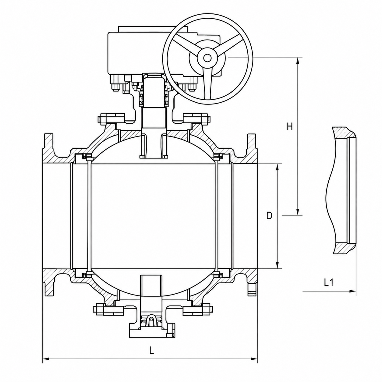
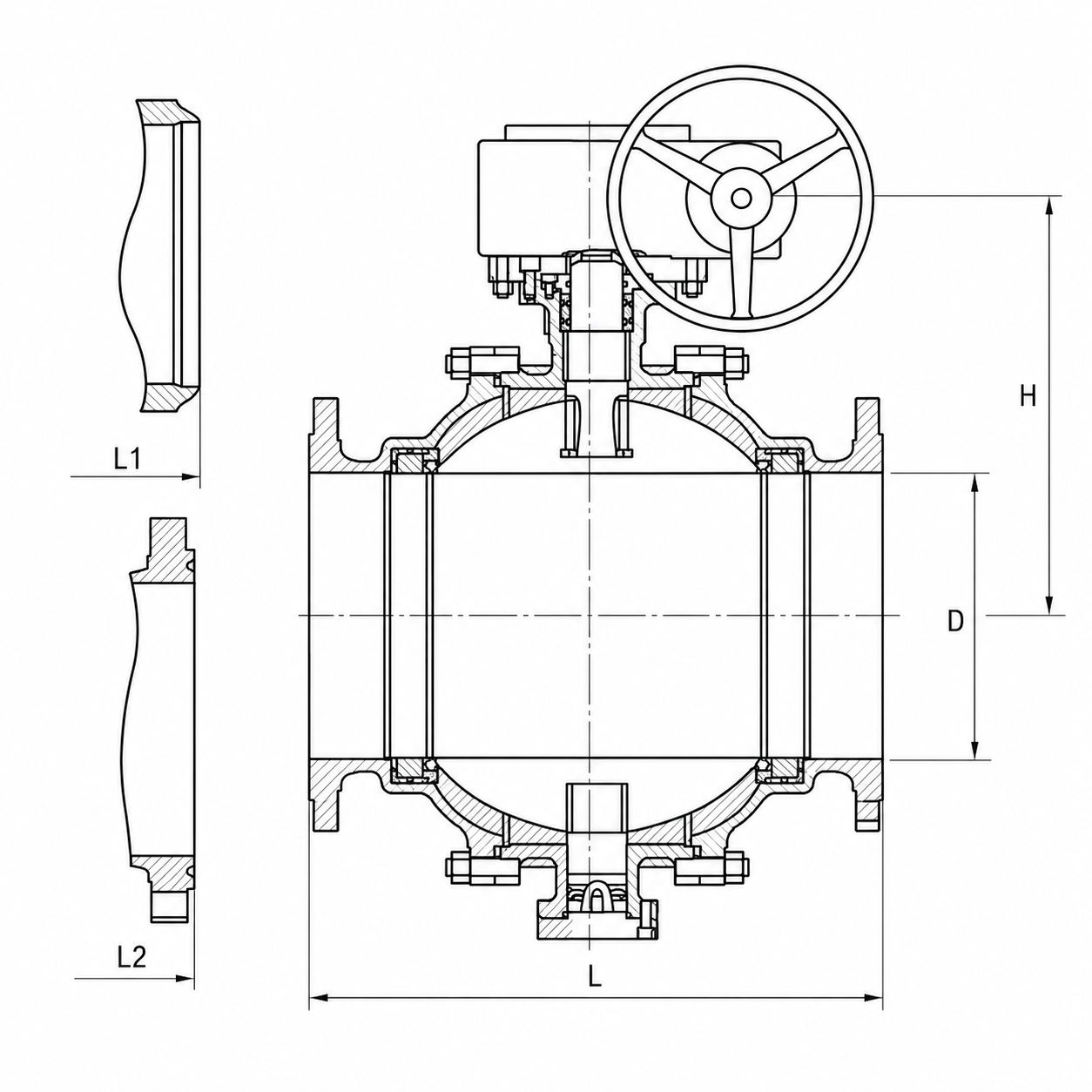
ANSI Class 150Lb
| Item | 2 | 2 1/2 | 3 | 4 | 6 | 8 | 10 | 12 | 14 | 16 | 18 | 20 | 24 | 26 | 28 | 30 | 32 | 36 |
|---|---|---|---|---|---|---|---|---|---|---|---|---|---|---|---|---|---|---|
| RF L | 178 | 190 | 203 | 229 | 394 | 457 | 533 | 610 | 686 | 762 | 864 | 914 | 1067 | 1143 | 1245 | 1295 | 1372 | 1524 |
| BW L1 | 216 | 241 | 283 | 305 | 457 | 521 | 559 | 635 | 762 | 838 | 914 | 991 | 1143 | 1245 | 1346 | 1397 | 1524 | 1727 |
| H | 177 | 190 | 210 | 235 | 530 | 625 | 650 | 780 | 790 | 920 | 970 | 1100 | 1150 | 1290 | 1400 | 1630 | 1840 | 2050 |
| d | 49 | 62 | 74 | 100 | 150 | 201 | 252 | 303 | 334 | 385 | 436 | 487 | 589 | 633 | 684 | 735 | 779 | 874 |
| W | 350 | 400 | 500 | 500 | 600 | 600 | 600 | 600 | 800 | 800 | 800 | 800 | 800 | 800 | 800 | 800 | 800 | 800 |
ANSI Class 300Lb
| Item | 2 | 2 1/2 | 3 | 4 | 6 | 8 | 10 | 12 | 14 | 16 | 18 | 20 | 24 | 26 | 28 | 30 | 32 |
|---|---|---|---|---|---|---|---|---|---|---|---|---|---|---|---|---|---|
| RF L | 216 | 241 | 283 | 305 | 403 | 502 | 568 | 648 | 762 | 838 | 914 | 991 | 1143 | 1245 | 1346 | 1397 | 1524 |
| BW L1 | 216 | 241 | 283 | 305 | 403 | 521 | 559 | 635 | 762 | 838 | 914 | 991 | 1143 | 1245 | 1346 | 1397 | 1524 |
| H | 177 | 190 | 210 | 235 | 530 | 625 | 650 | 780 | 790 | 920 | 970 | 1100 | 1150 | 1290 | 1400 | 1630 | 1800 |
| d | 49 | 62 | 74 | 100 | 150 | 201 | 252 | 303 | 334 | 385 | 436 | 487 | 589 | 633 | 684 | 735 | 779 |
| W | 350 | 400 | 500 | 500 | 600 | 600 | 600 | 600 | 800 | 800 | 800 | 800 | 800 | 800 | 800 | 800 | 800 |
ANSI Class 600Lb
| Item | 2 | 2 1/2 | 3 | 4 | 6 | 8 | 10 | 12 | 14 | 16 | 18 | 20 | 24 | 26 | 28 |
|---|---|---|---|---|---|---|---|---|---|---|---|---|---|---|---|
| RF L | 292 | 330 | 356 | 432 | 559 | 660 | 787 | 838 | 889 | 991 | 1092 | 1194 | 1397 | 1448 | 1549 |
| BW L1 | 295 | 333 | 359 | 435 | 562 | 664 | 791 | 841 | 892 | 994 | 1095 | 1200 | 1407 | 1461 | 1562 |
| H | 180 | 193 | 215 | 241 | 540 | 635 | 665 | 790 | 810 | 925 | 985 | 1130 | 1185 | 1335 | 1450 |
| d | 49 | 62 | 74 | 100 | 150 | 201 | 252 | 303 | 334 | 385 | 436 | 487 | 589 | 633 | 684 |
| W | 350 | 400 | 500 | 500 | 600 | 600 | 600 | 600 | 800 | 800 | 800 | 800 | 800 | 800 | 800 |
ANSI Class 900Lb
| Item | 2 | 2 1/2 | 3 | 4 | 6 | 8 | 10 | 12 | 14 | 16 | 18 | 20 | 24 |
|---|---|---|---|---|---|---|---|---|---|---|---|---|---|
| RF L | 368 | 419 | 381 | 457 | 610 | 737 | 838 | 965 | 1029 | 1130 | 1219 | 1321 | 1549 |
| BW L1 | 371 | 422 | 384 | 460 | 613 | 740 | 841 | 968 | 1038 | 1140 | 1232 | 1334 | 1568 |
| H | 219 | 235 | 260 | 390 | 655 | 770 | 805 | 965 | 980 | 1145 | 1195 | 1360 | 1425 |
| d | 49 | 62 | 74 | 100 | 150 | 201 | 252 | 303 | 322 | 373 | 423 | 471 | 570 |
| W | 500 | 500 | 500 | 600 | 600 | 600 | 600 | 800 | 800 | 800 | 800 | 800 | 800 |
Note: The catalog source lists RF L / BW L1 for NPS 3 as 381 / 384. Keep these source values unless corrected by an approved drawing.
ANSI Class 1500Lb
| Item | 2 | 2 1/2 | 3 | 4 | 6 | 8 | 10 | 12 | 14 | 16 |
|---|---|---|---|---|---|---|---|---|---|---|
| RF / BW L1 / L2 | 368 | 419 | 470 | 546 | 705 | 832 | 991 | 1130 | 1257 | 1384 |
| RTJ L2 | 371 | 422 | 473 | 549 | 711 | 841 | 1000 | 1046 | 1276 | 1407 |
| H | 285 | 306 | 338 | 506 | 852 | 1000 | 1045 | 1255 | 1270 | 1485 |
| d | 49 | 62 | 74 | 100 | 144 | 192 | 239 | 287 | 315 | 360 |
| W | 500 | 500 | 600 | 600 | 600 | 800 | 800 | 800 | 800 | 800 |
ANSI Class 2500Lb
| Item | 2 | 2 1/2 | 3 | 4 | 6 | 8 | 10 | 12 |
|---|---|---|---|---|---|---|---|---|
| RF / BW L1 / L2 | 451 | 508 | 578 | 673 | 914 | 1022 | 1270 | 1422 |
| RTJ L2 | 454 | 540 | 584 | 683 | 927 | 1038 | 1292 | 1445 |
| H | 304 | 327 | 362 | 540 | 811 | 1070 | 1120 | 1345 |
| d | 42 | 52 | 62 | 87 | 131 | 179 | 223 | 265 |
| W | 500 | 600 | 600 | 600 | 800 | 800 | 800 | 800 |
Design and Construction Options
Available construction options may include handle, worm gear, electric, pneumatic or hydraulic operation; full bore or reducing bore selection; raised face, ring type joint or butt-welded end connections; PTFE or graphite packing options; anti-static design; fire-safe design; injection/sealant fittings; and fixed ball bearing support according to service conditions.
For fire-safe, anti-static or injection service requirements, the final configuration should be confirmed according to the required project standard, medium, temperature, pressure class and inspection requirements.
Applications
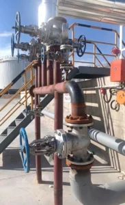
- Oil and gas pipeline isolation
- Petrochemical and refinery process lines
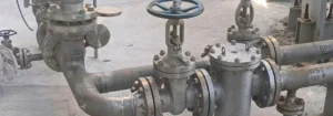
- General industrial ANSI pipeline systems
- Water, steam, oil and compatible gas service
- Large-size or higher-pressure quarter-turn shut-off service
- Projects requiring API 608 / API 6D ball valve references
Standards and Compliance
- Design reference: API 608 / API 6D
- Pressure-temperature reference: ASME B16.34
- Face-to-face reference: ASME B16.10
- Flange reference: ASME B16.5
- Butt-weld end reference: ASME B16.25
- Fire-safe reference: API 607 or BS 6755
- Anti-static reference: API 608
- Test and inspection reference: API 598 / API 6D
Technical data is based on catalog reference information. Final dimensions, material grades, seat materials and end connections should be confirmed according to project specification and approved drawings.
Frequently Asked Questions
What is HN106 mainly used for?
HN106 is mainly used for quarter-turn shut-off service in ANSI pipeline systems, including oil, gas, petrochemical, water, steam and compatible industrial media.
What is the difference between HN106 and HN105?
HN106 is a fixed ball valve designed for larger sizes or higher pressure classes, while HN105 is a floating ball valve for compact quarter-turn shut-off service. Final selection should be based on size, pressure class, operating torque and project specification.
Which pressure classes are available?
The catalog reference covers Class 150, Class 300, Class 600, Class 900, Class 1500 and Class 2500. The available size range depends on the selected pressure class and end connection.
Can HN106 be supplied with RF, BW or RTJ ends?
Yes. Raised face flange, butt-welded and ring type joint end configurations may be selected according to pressure class, piping design and project specification.
Is HN106 fire-safe and anti-static?
Fire-safe and anti-static construction may be selected according to API 607, BS 6755 and API 608 project requirements. Final configuration should be confirmed before quotation.
Related Resources
For larger chemical process lines and shut-off service, review these chemical processing valve selection notes.
For detailed selection guidance, read our API gate valve and ball valve selection guide.
Related Technical Guides
For technical comparison resources, see our API gate valve and ball valve selection guide, our floating ball valve vs fixed ball valve selection guide for HN105 and HN106 comparison, and our tank farm ball valve selection notes.
Request Pricing and Technical Data
For current pricing, lead time or technical documentation for the Fixed Ball Valve HN106, contact Honiks Valve using the form below or send your inquiry directly by email.
Reviews
There are no reviews yet.