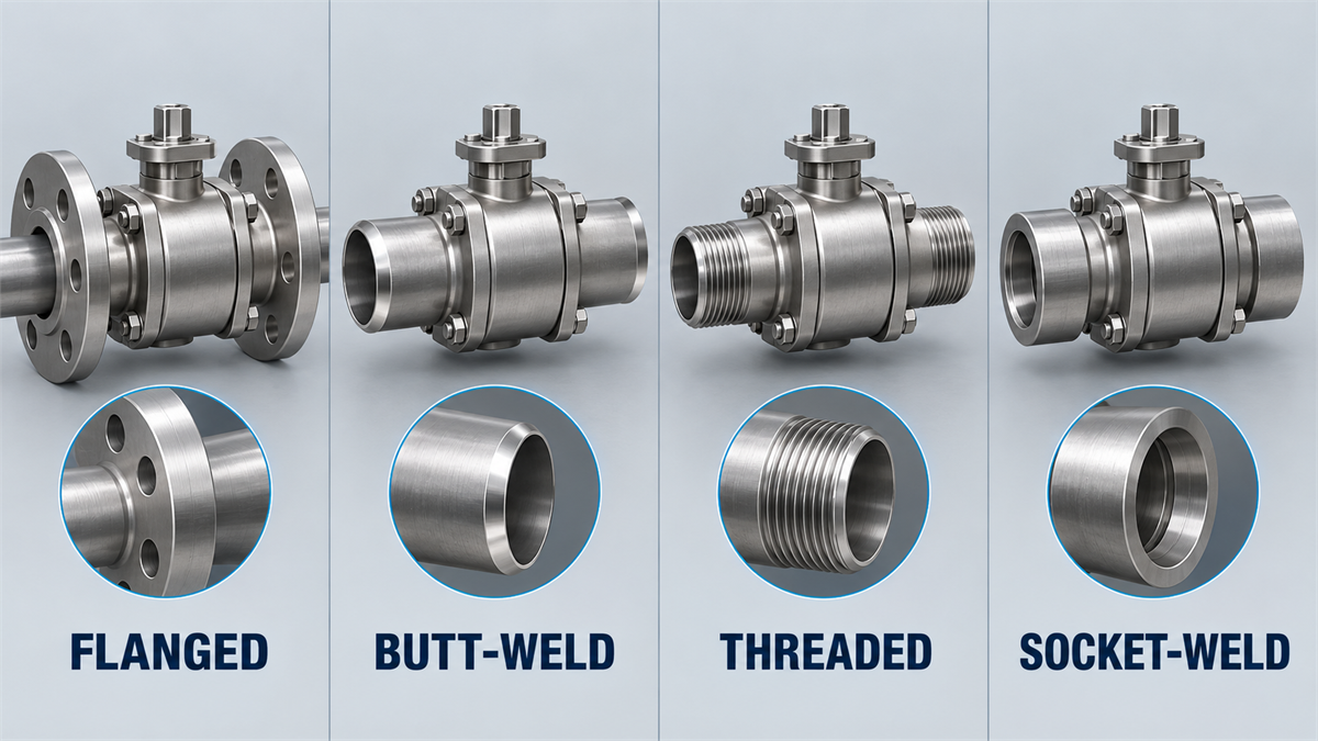
Short answer: select a ball valve end connection from the piping class, mating pipework, maintenance plan, installation method and required inspection evidence—not from pressure class or nominal size alone. Flanged ends provide a bolted, gasketed interface that may support planned removal. Butt-weld ends become part of a welded piping joint and require defined end preparation, welding and inspection controls. Threaded ends require an exact thread family, form and sealing method. Socket-weld ends are a separate welded interface and should not be treated as shorthand for butt-weld. The supplier should confirm the offered end geometry and drawing; the buyer should define the mating system and acceptance basis.
Decision Snapshot: Flanged, Butt-Weld, Threaded and Socket-Weld
| Decision area | Flanged | Butt-weld | Threaded | Socket-weld |
|---|---|---|---|---|
| Joint concept | Mating flanges, gasket or specified sealing element, and bolting | Prepared valve and pipe ends joined by an approved welding procedure | Compatible male/female threads assembled with the specified sealing basis | Pipe enters a machined socket and is joined by an external weld |
| Primary buyer input | Flange system, facing, rating designation, dimensions, gasket and bolting basis | End-preparation basis, pipe material/wall, transition details, welding and inspection requirements | Thread family, tapered/parallel form, gender, size, engagement and sealing method | Socket detail, pipe dimensions/material, fit-up, welding and examination requirements |
| Maintenance consequence | Removal may be planned if isolation, supports, clearance and flange separation are available | Removal normally changes the welded piping boundary and needs an approved field plan | Disassembly may require rotation, a union, spool movement or other layout allowance | Removal normally requires work on the welded joint or adjoining spool |
| Main comparison evidence | Approved flange/facing drawing and mating-component compatibility | Approved weld-end drawing, material identity and fabrication/inspection plan | Thread designation, gaging/inspection basis and assembly instructions | Approved socket detail and welding/inspection plan |
This table does not assign universal service limits. The complete valve design, body and trim materials, seat system, piping design, applicable standard edition and purchaser specification control whether an end connection is acceptable.
Start with the Piping Class, Not the Valve Catalog
The end connection is the interface between the valve and the adjacent piping. A catalog description such as “flanged,” “BW” or “threaded” is not enough to prove compatibility. Begin with the piping material specification, line class, valve datasheet, project standard and approved piping arrangement. These documents should identify the connection family and the dimensions, materials and acceptance evidence that govern the joint.
Keep four decisions separate:
- Product-standard scope: use the API 608 vs API 6D ball valve guide to identify the governing route without assuming the end connection from the standard number.
- Ball support: floating and fixed/trunnion arrangements are construction choices, not connection types.
- Flow passage: use the full-bore vs reduced-bore guide to specify the passage and its evidence separately.
- Seat system: temperature, media, solids, shutoff and test expectations remain separate from the valve-to-pipe joint.
API publicly lists API 608 as covering metal ball valves with flanged, threaded and butt-welding ends. That scope confirms that more than one connection route exists; it does not make those routes interchangeable or remove the purchaser’s responsibility to state the required interface.
When a Flanged Ball Valve Is the Better Project Route
A flanged valve connects to matching pipe flanges through bolting and a specified sealing interface. It can be a practical route when the maintenance strategy requires planned valve removal, when the piping class already uses flanged equipment interfaces, or when site fabrication rules favor mechanical assembly. Removal is not automatic: the line still needs safe isolation, drainage or depressurization where applicable, pipe support, access to bolting and enough separation to remove the valve without imposing uncontrolled loads.
What must match at the flange
- the governing flange standard and project edition;
- nominal size and pressure/rating designation;
- facing, surface-finish and gasket system;
- bolt-hole pattern, bolting basis and assembly procedure;
- face-to-face dimension and available installation envelope;
- materials, corrosion allowance or overlay requirements where applicable;
- mating-pipe alignment, support and allowable external loads.
Raised face, flat face and ring-type joint describe flange-facing or sealing arrangements; they are not separate valve body or ball-support categories. Do not substitute RF for RTJ—or any other facing—because two items share the same nominal size and class. The approved line class, flange documents and valve drawing must agree.
The public HN105 floating ball valve and HN106 fixed ball valve pages show available flanged/welded routes at product-family level. Treat those pages as an inquiry route, not proof that every size, class, facing or material combination is available. The quotation and approved drawing must identify the offered connection.
When a Butt-Weld Ball Valve Should Be Reviewed
A butt-weld valve is joined directly to prepared pipe ends. This can align with a welded piping philosophy or a project that wants to avoid a bolted flange joint at that location. It does not remove the need to verify leakage performance: weld integrity, valve body joints, stem sealing, seat performance and the rest of the piping system remain separate acceptance subjects.
ASME’s public description of B16.25 covers preparation of buttwelding ends, including bevels and internal/external shaping. For an RFQ, the phrase “BW ends” should therefore be expanded into an approved end-preparation basis and drawing. Confirm:
- pipe and valve-end material compatibility;
- mating outside diameter, wall condition and any transition detail;
- required bevel/root arrangement and dimensional basis;
- corrosion allowance, weld overlay or internal-bore requirements where applicable;
- project WPS/PQR and welder-qualification responsibilities;
- preheat, interpass control, PWHT and examination requirements where applicable;
- how seats, seals, coatings and internal cleanliness will be protected during fabrication;
- field pressure testing, preservation and repair documentation.
Do not apply a generic internet instruction about valve position or cooling during welding. The approved manufacturer instruction and project welding procedure must define the installation sequence for the offered design. If future valve removal would require cutting or replacing a spool, include that consequence in the maintenance and shutdown plan before choosing the connection.
Threaded Ball Valves Need More Than the Word “NPT”
A threaded end can provide a compact mechanical interface where the piping class and service permit it, but “threaded” is not a complete specification. NPT, NPSC, BSPT, BSPP and other thread systems are not automatically compatible. Tapered and parallel threads may use different sealing principles, and male/female requirements affect the mating parts and installation sequence.
ASME’s public B1.20.1 description covers dimensions and gaging for several inch pipe-thread forms. A buyer should state the exact thread designation and project edition, not ask the supplier to infer it from geography or pipe size. The RFQ should also define:
- male or female valve ends and whether both ends are identical;
- the intended sealing method and media compatibility of any sealant;
- required engagement/gaging evidence and thread protection for shipment;
- assembly-torque or manufacturer-instruction requirements;
- wrenching locations so installation torque is not carried through sensitive valve parts;
- clearance for assembly and future removal, including unions or removable spools where needed.
Threaded construction should not be accepted or rejected from a universal size or pressure rule in this guide. The piping class, full valve rating, body material, thread design, service conditions and project restrictions decide applicability.
Socket-Weld Is Not the Same as Butt-Weld
Socket-weld ends use a machined socket into which the pipe is inserted before welding. Butt-weld ends align prepared component ends. These interfaces have different geometry, fit-up controls and inspection implications. If a supplier writes only “weld end,” ask whether the offer is butt-weld or socket-weld and require the corresponding drawing and preparation details.
For either welded route, the project should allocate responsibility for fit-up, consumables, welding qualification, heat control, examination, pressure testing and repair. The valve supplier confirms the offered end and material; the EPC, fabricator or purchaser controls the wider piping-system procedure unless the purchase contract states otherwise.
Five-Step End-Connection Selection Workflow
- Freeze the governing documents. Record the line class, piping specification, valve datasheet, applicable standards/editions and approved deviations.
- Define the mating interface. State flange/facing, weld-end preparation, socket detail or thread family instead of a generic connection label.
- Review installation and maintenance. Check alignment, supports, access, hot-work restrictions, site capability, removal path and shutdown consequences.
- Allocate evidence responsibilities. Identify who supplies drawings, material records, welding documents, inspection reports and pressure-test records.
- Normalize supplier bids. Compare the exact offered interface, exclusions and deviations before comparing price or lead time.
For a broader line-item structure, combine this workflow with the API 6D ball valve RFQ checklist or the general industrial valve inquiry checklist.
Quote-Comparison Matrix
| RFQ subject | Buyer / EPC states | Supplier confirms | Evidence before approval |
|---|---|---|---|
| Connection identity | Required family and governing project document | Exact offered end on both sides | Datasheet and general arrangement drawing |
| Flanged interface | Standard, facing, rating designation, gasket/bolting basis | Dimensions, facing and material of offered flanges | Approved drawing and dimensional report |
| Butt-weld interface | Pipe material/wall and end-preparation requirement | Valve-end material, geometry and transition | Approved end-detail drawing and material records |
| Threaded interface | Thread family/form, gender and sealing method | Machined thread designation and inspection basis | Drawing, gaging or inspection record as specified |
| Socket-weld interface | Pipe dimensions/material and project fit-up requirement | Socket geometry and material | Approved drawing and fabrication plan |
| Installation controls | Site access, supports, welding/hot-work and maintenance constraints | Manufacturer installation limitations | Installation instruction and approved method statement |
| Testing/documents | Required ITP, hold points, reports and release dossier | Included tests/documents and deviations | Approved ITP and document register |
22 RFQ Fields for Ball Valve End Connections
- line number and service;
- design and operating pressure/temperature;
- fluid composition, phase and relevant hazards;
- nominal size and pressure/rating designation;
- piping material specification and line class;
- governing valve/product standard and contractual edition;
- required connection family at each end;
- flange standard and facing, when applicable;
- gasket and bolting basis, when applicable;
- thread family, form, gender and sealing method, when applicable;
- butt-weld end-preparation basis and mating pipe wall, when applicable;
- socket-weld detail and fit-up requirement, when applicable;
- face-to-face or end-to-end requirement;
- bore/minimum-passage and pigging requirement stated separately;
- body, end and weld-overlay materials;
- corrosion allowance and transition details;
- allowable external-load or support information;
- manufacturer installation/heat-protection instructions;
- welding, PWHT and NDE responsibilities where applicable;
- pressure-test and acceptance basis;
- drawing, material and inspection document deliverables;
- supplier deviations, exclusions and assumptions.
The valve testing and documentation checklist can be used to convert the last fields into an ITP and release-document review. Honiks’ Quality Control page provides the current public inspection route; project-specific witness points and records still need agreement in the quotation.
Common Specification Mistakes
- Writing “standard flange.” This omits the flange system, facing, dimensions, gasket and bolting basis.
- Treating RF and RTJ as interchangeable. They are different sealing interfaces and must match the line specification.
- Writing only “BW.” The end preparation, mating pipe wall/material and transition remain undefined.
- Using NPT and BSP as synonyms. Thread family and form must be explicit.
- Assuming a removable connection guarantees easy maintenance. Access, supports, isolation and spool movement still control removal.
- Assuming welded means leak-proof. Joint quality and all other valve/piping leak paths remain subject to design, fabrication and testing.
- Letting the connection imply the bore or seat. End connection, passage, ball support and seat system are separate selections.
Frequently Asked Questions
Is a butt-weld ball valve always better than a flanged ball valve?
No. A butt-weld route may fit a welded piping philosophy, while a flanged route may better support planned removal or an existing flange system. Service conditions, piping class, installation capability, maintenance strategy and required evidence determine the better route.
Does API 608 select the ball valve end connection?
No. API’s public catalog title shows that API 608 covers multiple end families. The purchaser still needs to state the required connection and mating-system details, and the supplier needs to confirm the exact offered configuration.
Are RF and RTJ separate valve connection types?
They are flange-facing/sealing arrangements within the broader flanged connection family. The specified facing must match the mating flange and project sealing system.
Can a threaded ball valve replace a flanged valve?
Only after the piping class, service, mechanical layout, thread system, rating and project approval are reviewed. A connection change is an interface change, not a catalog substitution.
What should be compared before choosing the lowest bid?
Compare the offered end identity, mating dimensions, facing/thread/weld preparation, materials, installation limits, testing/documents and deviations. Price comparison is meaningful only after those fields are normalized.
Prepare a Connection-Complete Ball Valve Inquiry
Review the current ball valve range, then send the line list, piping class, service data, required connection at each end, mating-component details, bore requirement, materials, testing and document list. Contact Honiks for a project review. The final valve, end connection, standards, inspection scope and documentation depend on the offered configuration, approved drawings and project specification.