A single leaking valve on a main steam line can take a generating unit offline. The root cause is not always the valve body — it is a bonnet joint that loosened after a thermal cycle, a gate disc eroded from unintended throttling, or a material grade one notch too low for the service temperature. In power plant piping above Class 900, the pressure seal bonnet design addresses the first two problems. The third comes down to matching material grade to service conditions — and that is where pressure seal valve selection becomes a specification exercise rather than a catalogue pick.
Pressure seal valves for power plant piping serve main steam, hot reheat, cold reheat, high-pressure feedwater, startup drains, turbine bypass, and auxiliary steam systems. For engineers and procurement teams preparing a valve RFQ, understanding where a pressure seal gate valve fits and where a pressure seal globe valve is needed helps avoid misapplication that shows up as seat leakage, stem binding, or excessive actuator torque months after commissioning. Honiks is a factory-backed industrial valve supplier based in China, supporting project inquiry review, inspection coordination, and documentation preparation for power plant valve supply.
Key Takeaways
- Pressure seal bonnet design uses system pressure to tighten the body-bonnet joint. This self-energizing principle is the reason pressure seal construction is standard above Class 900 in power plant piping.
- A pressure seal gate valve handles full-bore isolation on lines that stay open during normal operation. A pressure seal globe valve handles shut-off and throttling on bypass, drain, and feedwater control lines.
- Material grade follows steam temperature, not just pressure class. WC9 covers most supercritical and ultra-supercritical main steam service. Specifying it for a subcritical 450 deg C line is over-design — check the heat balance diagram.
- Inquiry packages for power plant valves include material certificates, pressure test records, dimensional reports, and NDE documentation. The inspection scope should be agreed at the quotation stage.
Where Pressure Seal Valves Are Used in Power Plant Piping
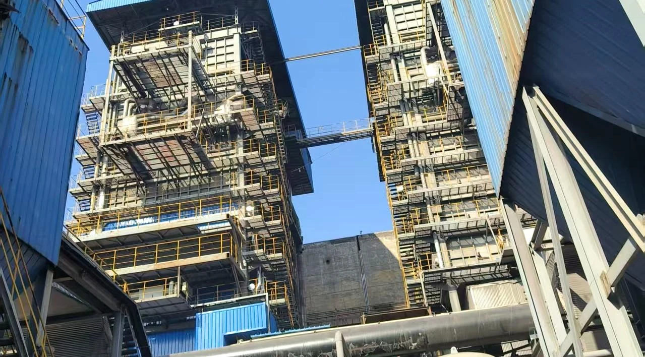
The high-pressure steam cycle has several locations where pressure seal gate or globe valves are specified. Main steam isolation — between the boiler outlet and the turbine inlet — is one of the most demanding. These valves hold at full Class 1500 or Class 2500 pressure with steam temperatures that may exceed 540 deg C, and they cycle from fully open to fully closed during unit startup and shutdown.
Hot reheat and cold reheat lines carry steam back to the boiler after partial expansion through the turbine. Gate valves on these lines provide full-bore isolation with low pressure drop. High-pressure feedwater lines from the boiler feed pump discharge to the economiser inlet run at pressures above the main steam pressure. Globe valves on feedwater bypass and recirculation lines control flow during low-load operation.
Startup drain and vent lines see the toughest thermal cycling — from ambient to full steam temperature in hours. Globe valves on these lines need stem and seat materials that hold dimensional stability through repeated heating and cooling. Turbine bypass valves manage steam flow around the turbine during startup and shutdown, requiring reliable throttling and tight shut-off when the bypass is closed. Auxiliary steam headers supply steam to soot blowers, air preheaters, and deaerators. See the Power Plant Solutions page for an overview of valve coverage across these services.
Why Pressure Seal Bonnet Design
A bolted bonnet relies on stud tension and gasket compression to seal the body-bonnet joint. As pressure and temperature rise, the bolts stretch, the gasket relaxes, and the joint becomes a potential leak path. In power plant piping above Class 900, the bolted bonnet flange becomes heavy, the stud count increases, and access for re-torquing during operation is impractical.
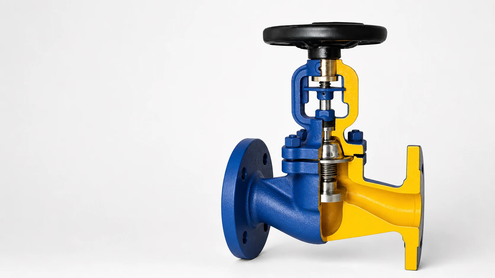
A pressure seal bonnet works on a different principle. The bonnet sits inside the body cavity, held by a segmented retaining ring. A graphite-based seal ring sits between the bonnet and body wall. When the line is pressurised, the process medium pushes the bonnet upward, compressing the seal ring radially against the body. Higher pressure produces a tighter seal — the joint self-energises.
Three practical advantages follow for high pressure steam valves. Weight drops by roughly 20-40 percent compared to an equivalent bolted bonnet design, because the heavy bonnet flange and bolt circle are eliminated. Maintenance is simpler at the joint — no stud re-torquing, no gasket replacement between cycles. Thermal cycling tolerance improves because the internal seal ring compensates for differential expansion between the body, bonnet, and seal material. The Gate Valves and Globe Valves categories include both bolted bonnet and pressure seal configurations for comparison.
Pressure Seal Gate Valve vs Pressure Seal Globe Valve
The gate valve vs globe valve power plant decision comes down to what the valve needs to do on the line. Gate valves isolate. Globe valves regulate. Getting this wrong means eroded seats on a gate valve used for throttling, or unnecessary pressure drop from a globe valve on a line that only needs to be open or closed.
| Selection factor | Pressure Seal Gate Valve | Pressure Seal Globe Valve | What matters for power plant |
|---|---|---|---|
| Primary duty | Full-bore on/off isolation | Shut-off plus throttling | Match valve function to the line duty, not to the catalogue description |
| Flow path | Straight-through when open; negligible pressure drop | S-shaped flow path; pressure drop even when fully open | Globe valve pressure drop matters on large-diameter feedwater lines |
| Throttling | Not designed for it; partial opening causes seat wire-drawing | Designed for controlled throttling across the disc stroke | Startup drains and turbine bypass need globe valves for this reason |
| Operation frequency | Infrequent cycling — open during normal operation, closed for maintenance | Frequent operation — modulating during startup, low-load, and shutdown | Gate valves are low-cycle devices by design |
| Maintenance access | Bonnet held by segmented ring; seal ring is a wear item | Same bonnet design; disc and seat inspection needs bonnet removal | Both need planned outage access |
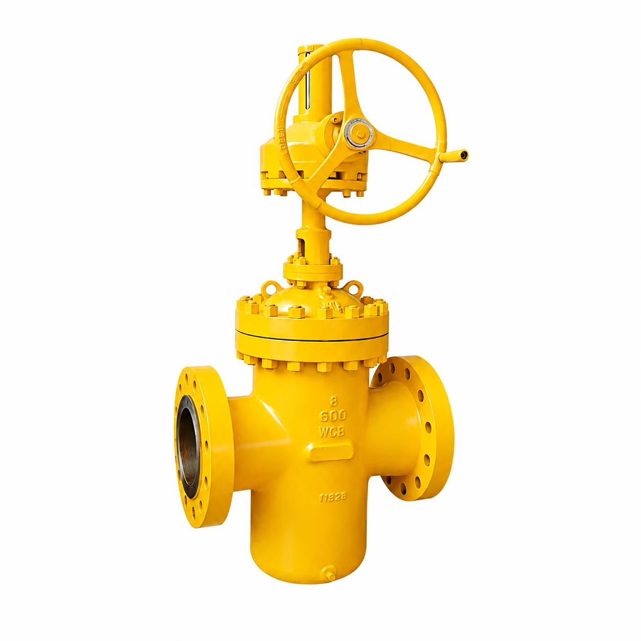
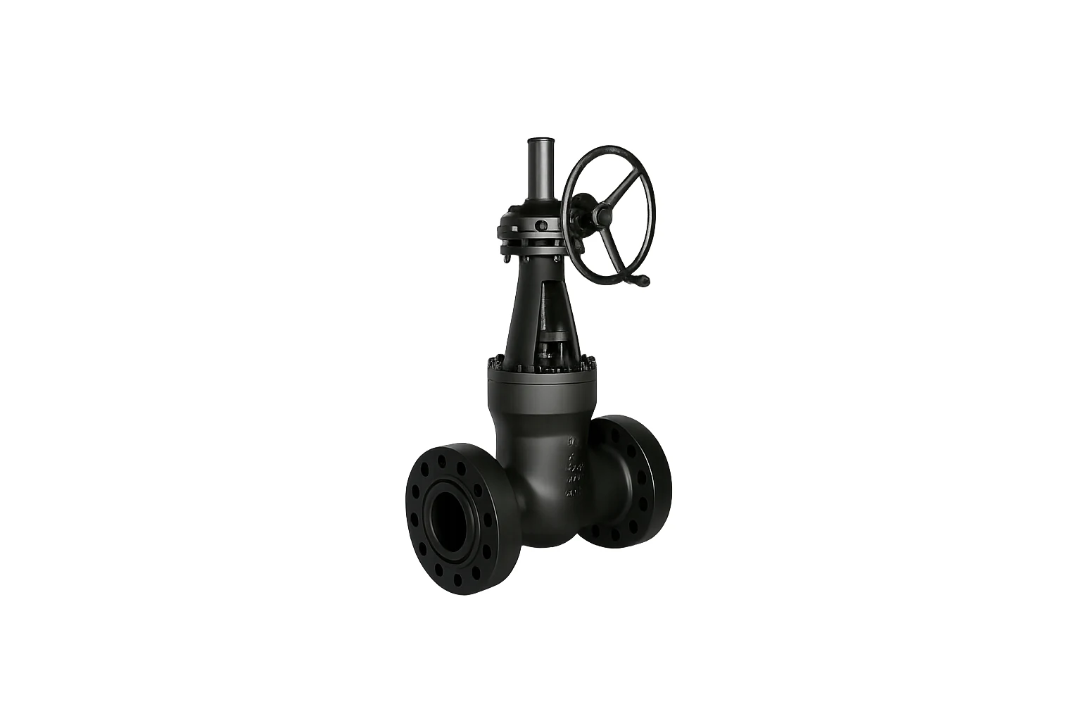
The Pressure Seal Gate Valve HN101 covers isolation duty from Class 900 through Class 2500. The Pressure Seal Globe Valve HN103 covers throttling and shut-off across the same pressure range. Dimensional data and material options are listed on the respective product pages.
Steam, Feedwater, Drain and Auxiliary Service
Each power plant service class imposes different demands on the valve. Main steam isolation valves operate at the highest combination of pressure and temperature on the unit, often Class 1500 or Class 2500 with superheated steam above 540 deg C. Gate valves are standard here — the line runs open during normal operation and the valve only cycles during unit starts and stops.
High-pressure feedwater presents a different challenge. The water is at a lower temperature than main steam, but the pressure is higher — the feed pump must overcome boiler pressure plus system losses. Globe valves on feedwater bypass and minimum-flow recirculation lines handle flow regulation during low-load operation when the main feedwater control valve is below its effective range.
Startup drains and vents experience the widest temperature swing. A drain valve at the bottom of a superheater header goes from ambient to full steam temperature in the time it takes to bring the boiler up to pressure. The globe valve trim must hold dimensional stability through this cycle, and the stem packing must seal reliably after repeated heating and cooling.
Turbine bypass and auxiliary steam services add throttling duty on top of isolation. Bypass valves modulate steam flow around the turbine during startup roll and shutdown cool-down. Auxiliary steam headers distributing steam to soot blowers and air preheaters need both isolation and flow control. Downstream of the feed pump, Check Valves prevent reverse flow when pumps cycle off. The API Swing Check Valve HN104 covers this duty in high-pressure feedwater discharge lines.
Material, Pressure Class and Temperature
Material selection for power plant valve selection follows the steam temperature, not just the pressure class. The following table outlines grades commonly referenced in power plant specifications. Availability should be confirmed against the project valve data sheet.
| Material | Typical service | Temperature range |
|---|---|---|
| A216 WCB | Saturated steam, low-temperature feedwater, auxiliary steam | -29 to 425 deg C |
| A217 WC6 | Main steam and hot reheat up to approximately 540 deg C | -29 to 540 deg C |
| A217 WC9 | Main steam, hot reheat for supercritical and ultra-supercritical units | -29 to 570 deg C |
| A217 C12A | Ultra-supercritical main steam above 570 deg C | -29 to 600+ deg C |
Pressure class is determined by the boiler design pressure and the piping specification. Class 900 covers many subcritical drum-type units. Class 1500 and Class 2500 are common on supercritical and ultra-supercritical once-through boilers. The applicable pressure-temperature rating should be confirmed against the ASME B16.34 table for the selected material group and the maximum design temperature.
End Connections and Operation Mode
Butt-weld ends to ASME B16.25 are the standard for pressure seal valves in power plant piping. The welded joint eliminates the flange gasket as a leak path, which matters on high-pressure steam and feedwater lines. Flanged ends to ASME B16.5 are used where periodic removal is expected — auxiliary steam headers, drain lines with strainers, and pump suction connections. The pipe schedule and bore should match the piping specification.
Manual operation with a handwheel covers most gate valves and smaller globe valves. Gear operators are fitted where handwheel effort exceeds the operator’s comfortable working range — above DN200 on Class 1500 gate valves. Electric actuators are specified where the valve is part of an automated startup sequence or a remote control loop from the DCS. For actuated valves, confirm the power supply voltage, the control signal type, the fail position, and the enclosure rating for the installation environment.
Inspection and Documentation
Power plant valve orders include a documentation package that is reviewed before shipment and filed for the life of the unit. The inspection scope should be agreed at the quotation stage and includes material test certificates to EN 10204 Type 3.1 or 3.2, confirming chemical composition and mechanical properties of the pressure-containing parts. API 598 hydrostatic shell and seat tests are standard, with test pressure, duration, and acceptance criteria documented per valve.
Non-destructive examination — radiography, ultrasonic testing, magnetic particle, or dye penetrant — may be specified on the valve data sheet for critical service locations. Dimensional inspection records confirm face-to-face, end connection, and overall dimensions. Coating and painting records are included where the project specification calls for a protective finish.
Honiks works with qualified partner factories to coordinate inspection and documentation for power plant valve orders. See the Factory Capability page for production and supply arrangements, and the Quality Control page for inspection management.
Buyer Inquiry Checklist
When preparing a valve RFQ for a power plant project, include the following for each line item:
- Valve type — pressure seal gate or pressure seal globe
- DN or NPS size
- Pressure class — Class 900, 1500, or 2500
- Body material — WCB, WC6, WC9, or C12A as specified
- Trim material — seat and disc overlay
- End connection — butt-weld or flanged
- Pipe schedule or wall thickness
- Operation — handwheel, gear, or electric actuator
- If actuated — voltage, signal, fail position, enclosure rating
- Service medium and design temperature
- Quantity per type, size, and class
- Documentation — MTC level, NDE scope, test reports
A complete inquiry returns a proposal covering scope, material lead time, and documentation plan in the first round — reducing the back-and-forth that delays purchase order placement.
Frequently Asked Questions
Is a pressure seal bonnet worth the cost for Class 600 lines in a power plant?
For Class 600 saturated steam or low-temperature feedwater, a bolted bonnet design is standard and adequate. The pressure seal design adds cost without a corresponding benefit at this pressure level. The transition to pressure seal construction occurs at Class 900, where the weight and reliability advantages of the self-energising joint become meaningful.
Which is more common on main steam isolation — gate or globe?
Gate valves are standard on main steam isolation. The line runs open during normal operation, so pressure drop matters more than throttling capability. Globe valves appear on main steam bypass, drain, and vent lines where flow regulation is required alongside shut-off.
What material grade is used for superheated steam above 540 deg C?
WC9 (2-1/4Cr-1Mo) covers main steam and hot reheat service up to approximately 570 deg C and is the most common grade for supercritical units. For ultra-supercritical plants with steam temperatures above 570 deg C, C12A (9Cr-1Mo-V) is specified. The material choice follows the boiler design temperature, not a default preference.
Can pressure seal gate and globe valves be supplied with butt-weld ends?
Butt-weld ends to ASME B16.25 are the standard end connection for pressure seal valves in power plant high-pressure piping. Flanged ends are available where periodic removal is expected. The end connection, pipe schedule, and bore size should be confirmed against the project piping specification.
Send Your Power Plant Valve Requirements
If the checklist above matches what you are preparing for a power plant valve RFQ, send the details and the Honiks team can return a proposal covering scope, material lead time, and documentation plan. Contact Honiks with your valve list, data sheet, or project specification for review.