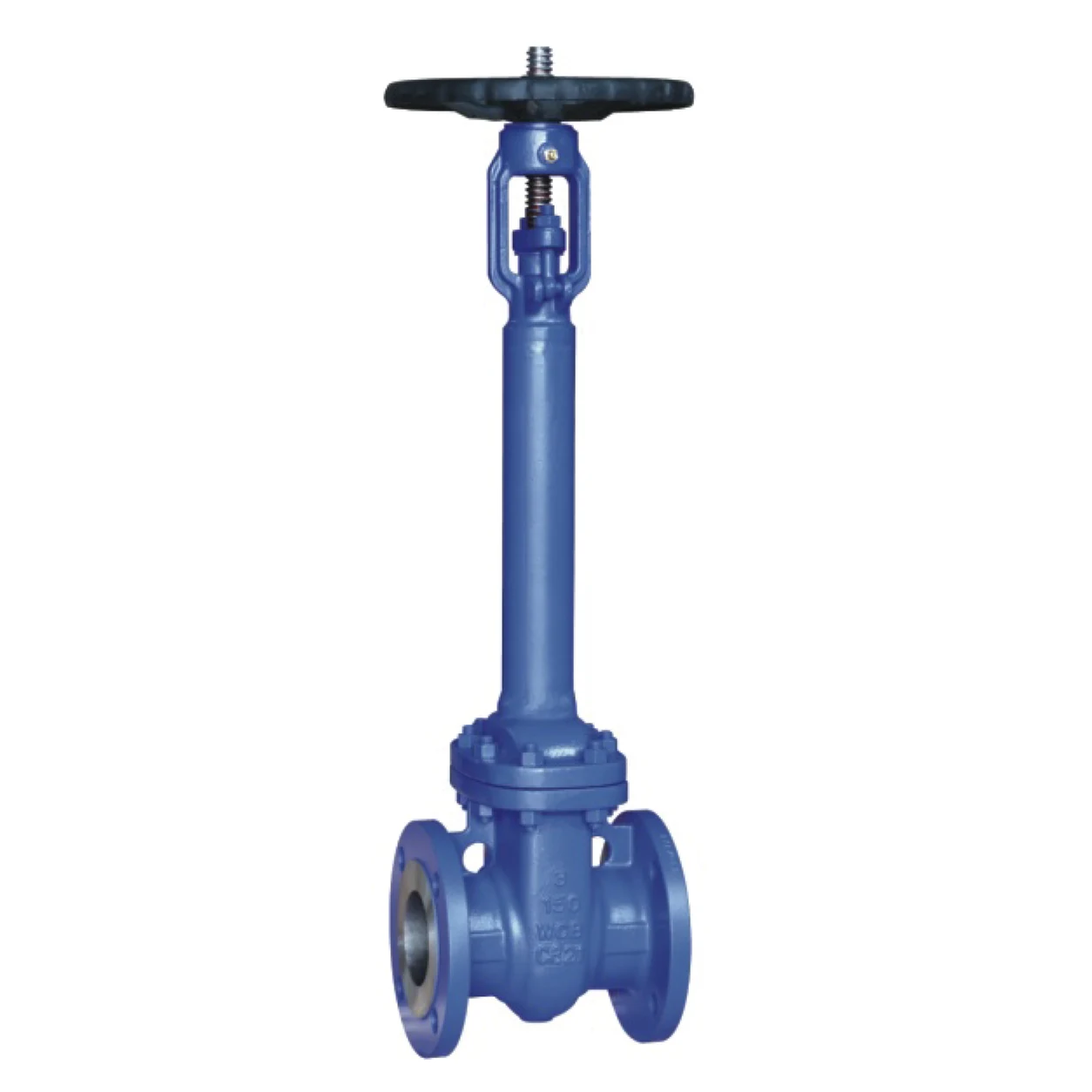
Product Overview
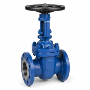
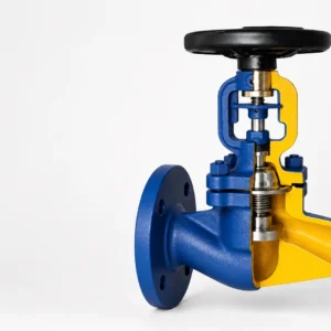
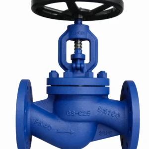
The HN70 Bellow Seal Globe/Gate Valve ANSI series covers larger ANSI class-rated bellow seal valve configurations for industrial pipeline service. It is available as globe valve or gate valve configurations, with flanged or butt-welded end connections and pressure classes from Class 150 to Class 1500.
HN70 is intended for applications where improved stem sealing reliability and reduced fugitive emission risk are important, such as steam systems, oil and gas pipelines, petrochemical plants, chemical processing, power engineering and general industrial service. The bellow seal assembly works together with secondary packing to help contain media around the stem area under compatible operating conditions.
Final configuration should be selected according to valve type, size, pressure class, body material, end connection, operation method and project documentation requirements.
Key Features
- ANSI class-rated bellow seal globe and gate valve series.
- Size range: 2 inch to 16 inch.
- Pressure classes: Class 150, Class 300, Class 600, Class 900 and Class 1500.
- Flanged ends according to ANSI/ASME B16.5.
- Butt-welded ends according to ANSI/ASME B16.25.
- Gate valve design reference: API 600.
- Globe valve design reference: BS 1873.
- Face-to-face reference: ANSI/ASME B16.10.
- Manual handwheel operation as standard; electric actuator options can be discussed based on project requirements.
- Secondary graphite packing provides backup stem sealing support if the bellow assembly is damaged.
Technical Specifications
| Parameter | Specification |
|---|---|
| Product series | HN70 |
| Valve type | Bellow seal globe valve / bellow seal gate valve |
| Standard system | ANSI / ASME |
| Size range | 2 inch to 16 inch |
| Pressure class | Class 150 to Class 1500 |
| End connections | Flanged, butt-welded |
| Gate valve design reference | API 600 |
| Globe valve design reference | BS 1873 |
| Flanged connection | ANSI/ASME B16.5 |
| Butt-welded connection | ANSI/ASME B16.25 |
| Face-to-face | ANSI/ASME B16.10 |
| Testing reference | API 598 |
| Operation | Handwheel; electric actuator options project-dependent |
| Service media | Water, steam, air, petroleum products, natural gas, gas condensate, oxygen, compatible industrial fluids and non-aggressive gases |
Application, Installation and Operation
Application
- Closing or throttling service for liquid and gaseous media.
- Fluids include water, steam, air, crude petroleum and petroleum products, natural gas, gas condensate, process solutions, oxygen, liquid media and non-aggressive gases.
- Typical industries include power engineering, chemical plants, petrochemical plants and general industrial pipelines.
Installation
- Install in horizontal lines with the valve in upright position unless project drawings specify otherwise.
- Flow direction should follow the body mark.
- Confirm orientation, support and actuator clearance before installation.
Operation
- Handwheel operation.
- Electric actuator option can be discussed for project requirements.
- ISO 5210 actuator-ready flange can be supplied according to configuration.
Gate Valve Structure and Materials
The numbered sectional drawing corresponds to the position numbers in the materials table. Final material selection should be confirmed according to pressure class, temperature and fluid compatibility.
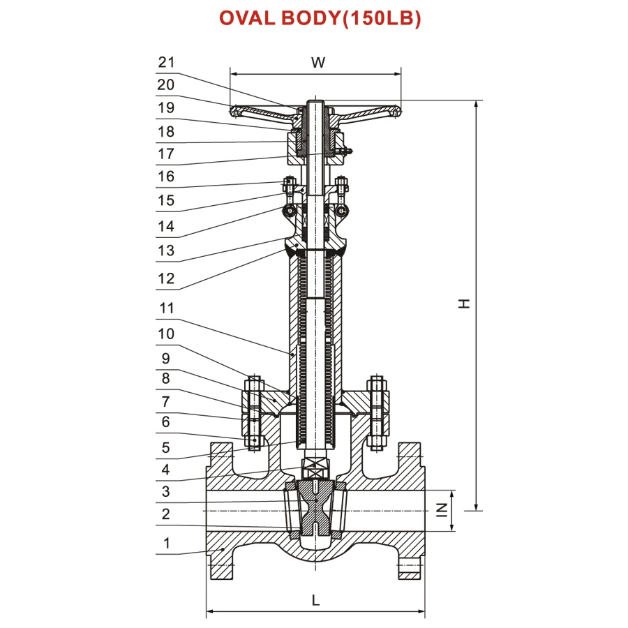
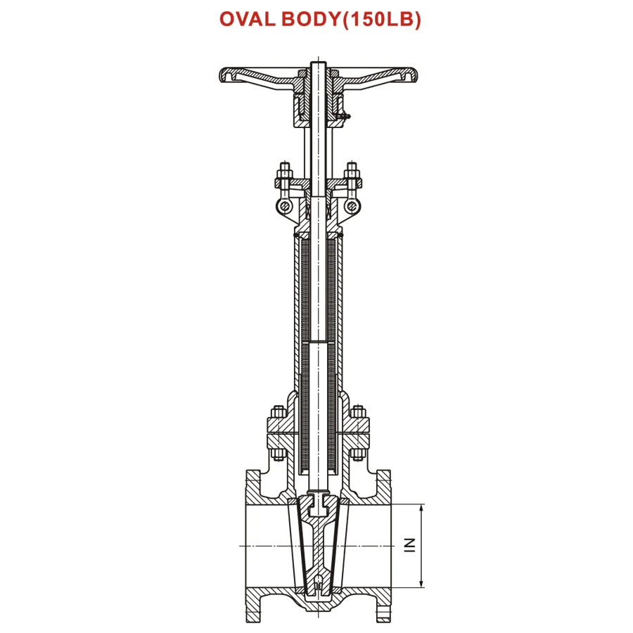
Materials of Main Parts — Gate Valve Configuration
| Pos. | Name | Material |
|---|---|---|
| 1 | Body | A216 WCB, A352 LCB, A182, A351 CF8/CF8M, A217 WC6 |
| 2 | Seat | 13Cr, STL6 |
| 3 | Wedge | A216 WCB, A352 LCB, A182, A351 CF8/CF8M, A217 WC6 |
| 4 | Stem | A182 F6a, A182 F304, A182 F316, A182 F11 |
| 5 | Bellows | SS304, SS316L |
| 6 | Nut | A194 2H, A194 8, A194 8M, A194 4 |
| 7 | Bolt | A193 B7, A193 B8, A193 B8M, A193 B16 |
| 8 | Gasket | Graphite + SS304 |
| 9 | Cover | A216 WCB, A352 LCB, A182, A351 CF8/CF8M, A217 WC6 |
| 10 | Guide pipe | Carbon steel, SS304, SS316 |
| 11 | Pipe | Carbon steel, SS304, SS316 |
| 12 | Yoke | A216 WCB, A352 LCB, A182, A351 CF8/CF8M, A217 WC6 |
| 13 | Packing | Graphite |
| 14 | Eyelet bolt | A193 B7, A193 B8, A193 B8M, A193 B16 |
| 15 | Gland | A216 WCB, A352 LCB, A182, A351 CF8/CF8M, A217 WC6 |
| 16 | Nut | A194 2H, A194 8, A194 8M, A194 4 |
| 17 | Grease nipple | Cu alloy |
| 18 | Stem nut | A276 410 |
| 19 | Screw | Carbon steel, stainless steel |
| 20 | Handwheel | A197 |
| 21 | Lock nut | ANSI 1035 |
Gate Valve Dimensions
Dimensions below are presented by pressure class. Final dimensions should be confirmed against approved drawings and engineering documentation for the specific material grade, pressure class and configuration.
Values marked with * are corrected from apparent source-catalog typographical errors and should be confirmed against approved drawings before quotation.
Gate Valve — Class 150
| Item | 2″ | 2 1/2″ | 3″ | 4″ | 5″ | 6″ | 8″ | 10″ | 12″ | 14″ | 16″ | 18″ | 20″ | 24″ |
|---|---|---|---|---|---|---|---|---|---|---|---|---|---|---|
| L RF | 178 | 191 | 203 | 229 | 254 | 267 | 292 | 330 | 356 | 381 | 406 | 432 | 457 | 508 |
| L BW | 216 | 241 | 282 | 305 | 381 | 403 | 419 | 457 | 502 | 571 | 610 | 660 | 711 | 813 |
| D | 152 | 178 | 191 | 229 | 254 | 278 | 343 | 406 | 483 | 533 | 597 | 635 | 699 | 813 |
| W | 200 | 200 | 225 | 250 | 250 | 300 | 400 | 500 | 500 | 600 | 600 | 700 | 700 | 800 |
| H | 610 | 675 | 820 | 940 | 1160 | 1530 | 1960 | 2350 | 2600 | 2980 | 3170 | 3550 | 4050 | 4650 |
Gate Valve — Class 300
| Item | 2″ | 2 1/2″ | 3″ | 4″ | 5″ | 6″ | 8″ | 10″ | 12″ | 14″ | 16″ | 18″ | 20″ | 24″ |
|---|---|---|---|---|---|---|---|---|---|---|---|---|---|---|
| L RF | 216 | 241 | 282 | 305 | 381 | 403 | 419 | 457 | 502 | 762 | 838 | 914 | 991 | 1143 |
| L BW | 232 | 257 | 298 | 321 | 397 | 419 | 435 | 473 | 518 | 778 | 854 | 930 | 1010 | 1165 |
| D | 165 | 191 | 210 | 254 | 279 | 318 | 381 | 445 | 521 | 584 | 648 | 711 | 775 | 914 |
| W | 200 | 200 | 225 | 250 | 300 | 400 | 500 | 500 | 600 | 600 | 700 | 700 | 800 | 900 |
| H | 600 | 685 | 765 | 920 | 1070 | 1315 | 1700 | 2035 | 2395 | 2760 | 3135 | 3600 | 4080 | 4795 |
Gate Valve — Class 600
| Item | 2″ | 3″ | 4″ | 6″ | 8″ | 10″ | 12″ | 14″ | 16″ | 18″ | 20″ | 24″ |
|---|---|---|---|---|---|---|---|---|---|---|---|---|
| L RF | 292 | 356 | 432 | 559 | 660 | 787 | 838* | 889 | 991 | 1092 | 1194 | 1397 |
| L BW | 295 | 359 | 435 | 562 | 663 | 791 | 841 | 892 | 994 | 1095 | 1200 | 1407 |
| D | 165 | 210 | 273 | 356 | 419 | 508 | 559 | 603 | 686 | 743 | 813 | 940 |
| W | 200 | 250 | 400 | 500 | 600 | 700 | 900 | 800 | 900 | 1000 | 1600 | G.O. |
| H | 640 | 805 | 905 | 1360 | 1720 | 2120 | 2500 | – | – | – | – | – |
Gate Valve — Class 900
| Item | 2″ | 3″ | 4″ | 6″ | 8″ | 10″ | 12″ | 14″ | 16″ |
|---|---|---|---|---|---|---|---|---|---|
| L RF | 368 | 381 | 457 | 610 | 737 | 838 | 965 | 1029 | 1130 |
| L BW | 371 | 384 | 460 | 613 | 740 | 841 | 968 | 1038 | 1140 |
| D | 216 | 241 | 292 | 381 | 470 | 546 | 610 | 641 | 705 |
| W | 250 | 300 | 400 | 600 | 650 | 700 | 900 | 1000* | G.O. |
| H | – | – | – | – | – | – | – | – | – |
Gate Valve — Class 1500
| Item | 2″ | 3″ | 4″ | 6″ | 8″ | 10″ | 12″ | 14″ | 16″ |
|---|---|---|---|---|---|---|---|---|---|
| L RF | 368 | 470 | 546 | 705 | 832 | 991 | 1130 | 1257 | 1384 |
| L BW | 371 | 473 | 549 | 711 | 842 | 1000 | 1146 | 1276 | 1407 |
| D | 216 | 267 | 311 | 394 | 483 | 584 | 673 | 749 | 826 |
| W | 250 | 400 | 500 | 600 | 700 | 900 | 1600 | 1600 | 1600 |
| H | – | – | – | – | – | – | – | – | – |
Globe Valve Structure and Materials
The numbered sectional drawing corresponds to the position numbers in the materials table. Final material selection should be confirmed according to pressure class, temperature and fluid compatibility.
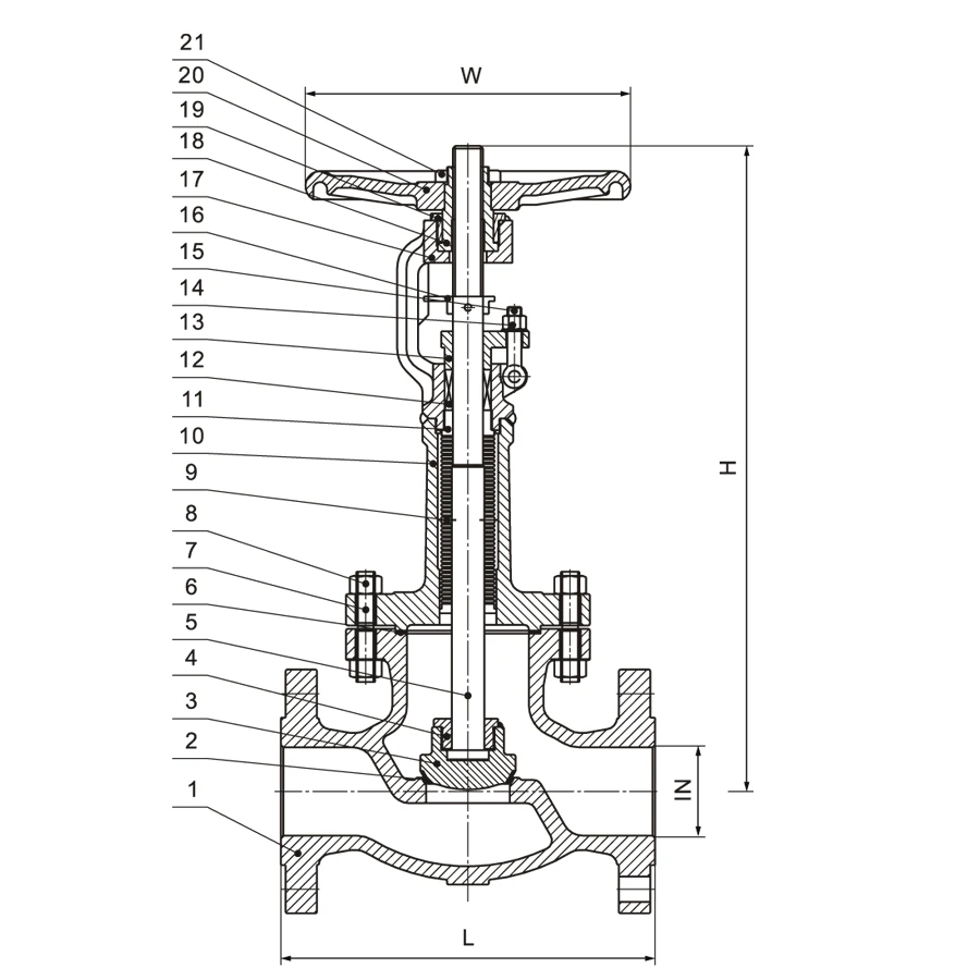
Materials of Main Parts — Globe Valve Configuration
| Pos. | Name | Material |
|---|---|---|
| 1 | Body | A216 WCB, A352 LCB, A182, A351 CF8/CF8M, A217 WC6 |
| 2 | Seat | 13Cr, STL6 |
| 3 | Disc | A216 WCB, A352 LCB, A182, A351 CF8/CF8M, A217 WC6 |
| 4 | Disc screw | Carbon steel, SS304, SS316 |
| 5 | Stem | A182 F6a, A182 F304, A182 F316, A182 F11 |
| 6 | Gasket | Graphite + SS304 |
| 7 | Bolt | A193 B7, A193 B8, A193 B8M, A193 B16 |
| 8 | Nut | A194 2H, A194 8, A194 8M, A194 4 |
| 9 | Bellows | SS304, SS316L |
| 10 | Cover | A216 WCB, A352 LCB, A182, A351 CF8/CF8M, A217 WC6 |
| 11 | Packing seat | SS304, SS316L |
| 12 | Packing | Graphite, PTFE |
| 13 | Gland | A216 WCB, A352 LCB, A182, A351 CF8/CF8M, A217 WC6 |
| 14 | Nut | A194 2H, A194 8, A194 8M, A194 4 |
| 15 | Eyelet bolt | A193 B7, A193 B8, A193 B8M, A193 B16 |
| 16 | No rotating device | A105, F304 |
| 17 | Yoke | A216 WCB, A352 LCB, A182, A351 CF8/CF8M, A217 WC6 |
| 18 | Stem nut | A276 410 |
| 19 | Screw | Carbon steel, stainless steel |
| 20 | Handwheel | A197 |
| 21 | Lock nut | ANSI 1035 |
Globe Valve Dimensions
Dimensions below are presented by pressure class. Final dimensions should be confirmed against approved drawings and engineering documentation for the specific material grade, pressure class and configuration.
Values marked with * are corrected from apparent source-catalog typographical errors and should be confirmed against approved drawings before quotation.
Globe Valve — Class 150
| Item | 2″ | 2 1/2″ | 3″ | 4″ | 5″ | 6″ | 8″ | 10″ | 12″ | 14″ | 16″ |
|---|---|---|---|---|---|---|---|---|---|---|---|
| L RF/BW | 203 | 216 | 241 | 292 | 356 | 406 | 495 | 622 | 699 | 787 | 914 |
| L RTJ | 216 | 219 | 254 | 305 | 368 | 419 | 508 | 635 | 711 | 800 | 927 |
| D | 152 | 178 | 191 | 229 | 254 | 279 | 343 | 406 | 483 | 533 | 597 |
| W | 200 | 200 | 200 | 250 | 300 | 300 | 400 | 500 | 500 | 600 | 600 |
| H | 340 | 370 | 400 | 440 | 500 | 580 | 700 | 800 | 900 | 970 | 1270 |
Globe Valve — Class 300
| Item | 2″ | 2 1/2″ | 3″ | 4″ | 5″ | 6″ | 8″ | 10″ | 12″ | 14″ | 16″ |
|---|---|---|---|---|---|---|---|---|---|---|---|
| L RF/BW | 267 | 292 | 318 | 356 | 400 | 445 | 533 | 622 | 711 | 838 | 864 |
| L RTJ | 282 | 308 | 333 | 371 | 416 | 460 | 549 | 638 | 727 | 854 | 879 |
| D | 165 | 191 | 210 | 254 | 279 | 318 | 381 | 445 | 521 | 584 | 648 |
| W | 200 | 200 | 250 | 300 | 300 | 400 | 500 | 500 | 500 | 600 | 600 |
| H | 410 | 420 | 430 | 544 | 590 | 820 | 880 | 950 | 1205* | 1200 | 1440 |
Globe Valve — Class 600
| Item | 2″ | 2 1/2″ | 3″ | 4″ | 5″ | 6″ | 8″ | 10″ | 12″ | 14″ | 16″ |
|---|---|---|---|---|---|---|---|---|---|---|---|
| L RF/BW | 292 | 330 | 356 | 432 | 508 | 559 | 660 | 787 | 838 | 889 | 991 |
| L RTJ | 295 | 333 | 359 | 435 | 511 | 562 | 663 | 790 | 841 | 892 | 994 |
| D | 165 | 191 | 210 | 273 | 330 | 356 | 419 | 508 | 559 | 603 | 686 |
| W | 200 | 250 | 250 | 300 | 350 | 400 | 500 | 500 | 600 | 600 | 600 |
| H | 370 | 525 | 565 | 620 | 700 | 800 | 860 | 1280 | 1350 | 1490 | 1720 |
Globe Valve — Class 900
| Item | 2″ | 2 1/2″ | 3″ | 4″ | 5″ | 6″ | 8″ | 10″ | 12″ |
|---|---|---|---|---|---|---|---|---|---|
| L RF/BW | 368 | 419 | 381 | 457 | 559 | 610 | 737 | 838 | 965 |
| L RTJ | 371 | 422 | 384 | 460 | 562 | 613 | 740 | 842 | 968 |
| D | 216 | 244 | 241 | 292 | 349 | 381 | 470 | 546 | 610 |
| W | 250 | 250 | 350 | 500 | 650 | 700 | 900 | 1000 | 1000 |
| H | 590 | 710 | 610 | 750 | 890 | 1000 | 1170 | 1540 | 1720 |
Globe Valve — Class 1500
| Item | 2″ | 2 1/2″ | 3″ | 4″ | 5″ | 6″ | 8″ | 10″ | 12″ |
|---|---|---|---|---|---|---|---|---|---|
| L RF/BW | 368 | 419 | 470 | 546 | 673 | 705 | 832 | 991 | 1130 |
| L RTJ | 371 | 422 | 473 | 549 | 676 | 711 | 842 | 1000 | 1146 |
| D | 216 | 244 | 267 | 311 | 375 | 394 | 483 | 574 | 673 |
| W | 250 | 250 | 400* | 500 | 700 | 900 | 1000 | 1000 | 1000 |
| H | 590 | 710 | 780 | 860 | 930 | 1000 | 1100 | 1720 | 1810 |
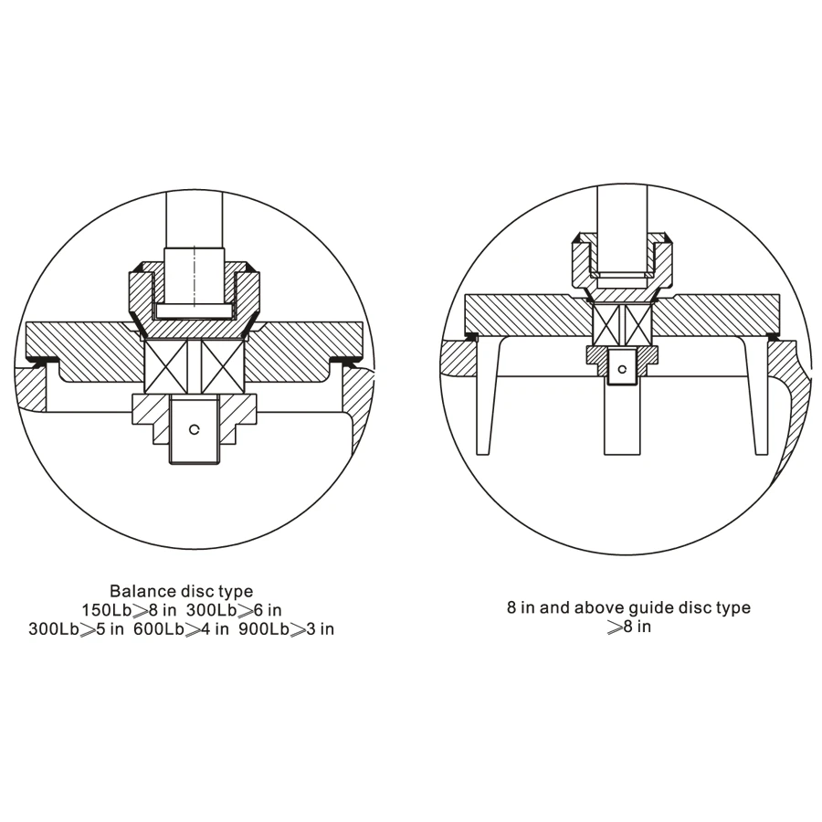
Globe Valve Disc Type Options
- Balance disc type: typically used for larger size and higher pressure class combinations. Source notes: 150LB > 8 in, 300LB > 5 in, 600LB > 4 in, 900LB > 3 in.
- Guide disc type: source notes 8 in and above.
- Final disc construction should be confirmed according to pressure class, size, operating differential pressure and service requirements.
Testing and Standards
- Gate valve design reference: API 600.
- Globe valve design reference: BS 1873.
- Flanged ends: ANSI/ASME B16.5.
- Butt-welded ends: ANSI/ASME B16.25.
- Face-to-face dimensions: ANSI/ASME B16.10.
- Pressure testing: API 598.
- Shell test: nominal pressure class × 1.5.
- Seat tightness test: nominal pressure class × 1.1.
FAQ
Q: Is HN70 a globe valve or a gate valve?
A: HN70 is a bellow seal ANSI valve series available in both globe valve and gate valve configurations. The final valve type should be confirmed according to the application, flow control requirement and shut-off requirement.
Q: What is the main difference between HN69 and HN70?
A: HN69 is a forged steel ANSI bellow seal valve series for smaller sizes. HN70 covers larger ANSI class-rated bellow seal globe and gate valve configurations from 2 inch to 16 inch.
Q: Can HN70 be supplied with butt-welded ends?
A: Yes. HN70 can be configured with flanged or butt-welded ends depending on project requirements.
Q: Are actuators available?
A: Manual handwheel operation is standard. Electric actuator options can be discussed based on project requirements.

Reviews
There are no reviews yet.