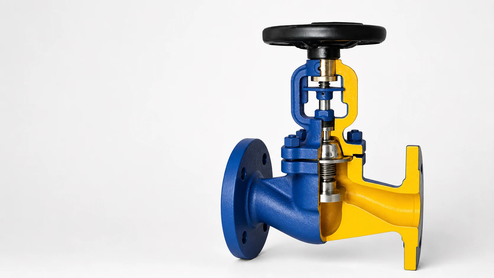
A butterfly valve on a DN600 cooling water line that fails to close during a pump trip can flood a pump room in minutes. The valve body is not the defect — it is the seat material that hardened after several summers of intermittent operation, or the gear operator that was undersized for the closing torque against differential pressure. In industrial water, HVAC utility and fire water piping, industrial butterfly valves are widely specified because of their compact body, quarter-turn operation and lower weight compared to multi-turn gate valves — but the selection details determine whether the valve operates reliably across its service life.
Butterfly valves for water piping serve chilled water and heating water distribution, cooling tower headers, condenser water supply and return, fire water ring mains, pump room suction and discharge headers, utility distribution lines, and water treatment plant transfer piping. Honiks is a factory-backed industrial valve supplier based in China, supporting project inquiry review, inspection coordination and documentation preparation for butterfly valve supply across these applications.
Key Takeaways
- Butterfly valves are selected for compact installation, quarter-turn operation and lower weight on water lines where full-bore pigging or zero pressure drop is not the primary requirement.
- Wafer pattern butterfly valves fit between standard pipe flanges without extra flange bolts, saving space and reducing installed weight on water distribution and utility headers.
- Seat material — EPDM for general water service, NBR where oil or hydrocarbon resistance matters, PTFE for higher temperatures or chemical resistance — directly affects temperature range, media compatibility and service life. Confirm the seat grade against the water chemistry data sheet.
- Gear operators are common above DN200 on butterfly valves used for water service where closing torque against differential pressure matters. Lever operation covers smaller sizes up to approximately DN200 where manual quarter-turn is adequate and operating torque is within comfortable range.
- Fire water piping is industrial water distribution. If the project specification requires listed fire protection equipment, the buyer must confirm those requirements independently. A butterfly valve selected for general water service is not automatically suitable for the listed equipment scope.
Where Butterfly Valves Are Used in Water, HVAC and Fire Water Piping
Butterfly valves appear wherever large-diameter water lines need reliable isolation in a compact footprint. The common thread across all these applications is the combination of short face-to-face dimension, low installed weight and quarter-turn operation that suits both manual and automated valve positions.
Water Treatment Plants
In municipal and industrial water treatment plants, butterfly valves are specified on raw water intake lines, filter inlet and outlet headers, backwash piping, sludge transfer lines and treated water distribution mains. On raw water and filter gallery headers above DN400, the weight difference between a butterfly valve and an equivalent gate valve can affect valve chamber dimensions, crane access planning and structural support requirements. The short face-to-face dimension allows tighter pipe rack spacing in treatment plant galleries where multiple parallel lines run side by side.
Electric actuation is common on butterfly valves in water treatment plants — the valve opens and closes as part of the filter backwash sequence or the treated water distribution programme controlled by the plant SCADA system. The actuator must be matched to the valve torque requirement, not simply selected by nominal size, and the enclosure rating should match the installation environment — indoor valve gallery, outdoor pipe bridge, or below-grade valve chamber. See the Water Treatment Solutions page and the industrial valves for water treatment plants guide for broader application context across treatment processes.
HVAC Chilled Water and Heating Water
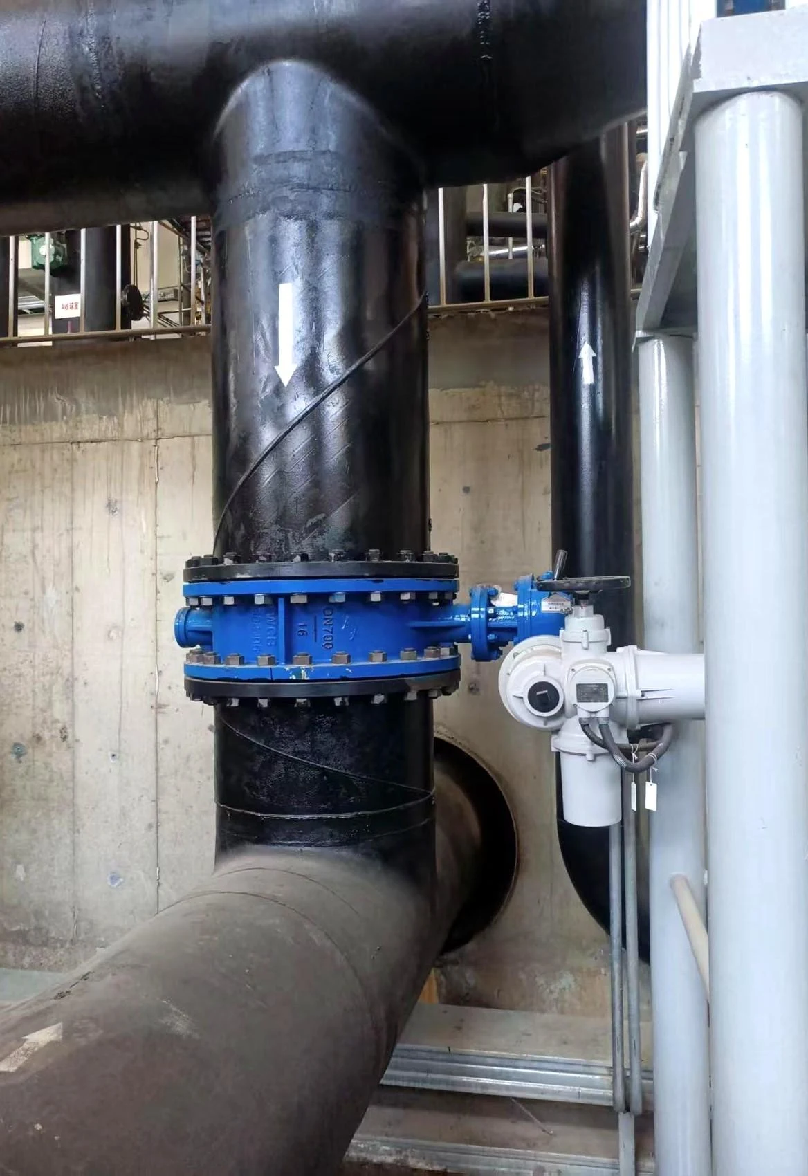
On chilled water and heating water distribution loops in commercial buildings, hospitals, data centres and industrial facilities, butterfly valves provide isolation at air-handling unit connections, fan coil unit branches, pump suction and discharge, chiller barrel isolation, cooling tower cell isolation and riser isolation at each floor take-off. The compact face-to-face dimension means the valve fits into congested mechanical rooms and ceiling-level pipe galleries where a multi-turn gate valve would require more installation length and more access clearance for the handwheel.
Gear-operated butterfly valves on larger chilled water headers allow one person to cycle the valve during seasonal changeover without excessive handwheel effort. On building management system controlled valves, electric actuators with 0-10V or 4-20mA position feedback integrate the butterfly valve into the central control sequence — opening and closing in response to chiller staging, pump changeover and cooling tower seasonal rotation. The HVAC Solutions page covers valve types across building utility services.
Cooling Water and Process Utility Piping
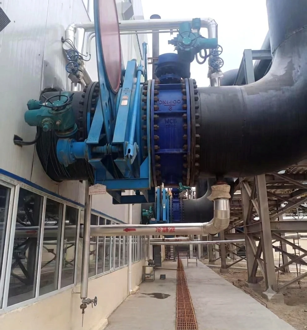
Cooling tower supply and return headers, condenser water lines serving process chillers and heat exchangers, and process cooling water loops in industrial plants use butterfly valves for isolation and flow direction control. On a cooling tower with multiple cells, a butterfly valve at each cell inlet allows one cell to be taken offline for maintenance while the remaining cells continue to operate — the quarter-turn operation makes this a quick manual task during a planned shutdown window.
Electric actuators are specified on large cooling water valves where remote operation from the plant control room is required during startup and shutdown sequences. For cooling water lines serving critical process equipment — where loss of cooling flow has a safety or production consequence — a pneumatic actuator with spring-return may be specified so that the valve moves to a pre-determined safe position on loss of instrument air or control signal.
Fire Water Mains and Industrial Fire Water Distribution
Fire water ring mains, hydrant supply headers and fire pump suction and discharge lines in industrial facilities, tank farms, process plants and power stations may use butterfly valves for sectional isolation. These are industrial water distribution valves installed on fire water pipework — they isolate sections of the ring main for maintenance, separate the hydrant network into controllable zones, and provide isolation at the fire pump set.
If a project specification requires fire protection equipment that is listed by a recognised testing laboratory or certified to a specific fire protection standard, the buyer must confirm those requirements against the project specification and purchase order documentation. A butterfly valve selected for general industrial water service does not automatically meet the listing requirements for an automatic sprinkler system or a deluge system installation. See the Fire Fighting Solutions page for an overview of industrial water valve coverage.
Pump Rooms and Utility Headers
On pump suction and discharge headers in water booster stations, HVAC pump rooms and cooling water pump sets, butterfly valves provide isolation with the shortest possible face-to-face dimension. A butterfly valve on the pump discharge, paired with a swing check valve immediately downstream, creates a compact pump control set that fits within the pump skid footprint. The combination of a butterfly isolation valve and a check valve minimises the pipe run between the pump discharge flange and the header connection.
The API Swing Check Valve HN104 covers backflow prevention in horizontal pump discharge lines. On vertical pump discharge lines or applications where water hammer is a concern, the check valve type should be reviewed against the pump curve and system hydraulics.
Why Butterfly Valves Are Selected for Water Service
Four practical factors drive butterfly valve specification across water, HVAC and utility projects. The body is compact — a wafer or lug butterfly valve has a face-to-face dimension that is a fraction of an equivalent gate valve, saving space in pipe galleries, mechanical rooms and valve chambers where multiple parallel lines compete for floor area. Weight is lower — a DN600 butterfly valve may weigh 60–70 percent less than a DN600 gate valve of the same pressure class, reducing the structural steel support requirements and allowing a smaller crane or manual lifting arrangement during installation.
Quarter-turn operation means the valve cycles from fully open to fully closed with a 90-degree rotation of the stem. Manual lever operation covers smaller sizes up to approximately DN200. Gear operators handle larger sizes and higher differential pressures by multiplying the handwheel input torque through a worm gear set. The self-locking characteristic of a worm gear operator holds the disc in position against flow forces — no separate locking mechanism is needed. Automation is simpler than multi-turn valves because the actuator only needs a 90-degree stroke. An electric actuator fitted to a butterfly valve is a standard configuration for remote operation from a DCS, SCADA or building management system.
Cost on large diameters is generally lower for butterfly valves compared to gate valves. Less body material, simpler machining and fewer internal components contribute to a lower manufactured cost — and that cost difference increases with diameter. On a project with multiple DN500 and DN600 isolation points, the accumulated saving across the valve schedule can be significant. The Wafer Butterfly Valve HN107 covers wafer pattern butterfly configurations for water, HVAC and utility piping. The Butterfly Valves category includes additional configurations for project comparison.
Butterfly Valve vs Gate Valve for Water Service
The decision between a butterfly valve and a gate valve for water service comes down to what the line needs most — minimal installed size and lower cost on large diameters, or full-bore flow with zero obstruction and the ability to pig the line.
| Selection Factor | Butterfly Valve | Gate Valve | What to Check for Water Service |
|---|---|---|---|
| Face-to-face dimension | Short — wafer body fits between flanges | Longer — body length increases with diameter | Check available pipe gallery or valve chamber clearance before finalising valve type |
| Weight on large diameters | Lower — disc and body are inherently lighter than a gate wedge and body | Higher — body mass and wedge weight scale with diameter | Crane access, lifting plan and support steel may influence the choice above DN400 |
| Pressure drop when fully open | Disc remains in the flow path — some restriction exists | Full-bore — straight-through flow with negligible restriction | On gravity-fed or low-head lines, confirm the butterfly valve pressure drop against available system head |
| Throttling capability | Disc can be positioned at intermediate angles for flow modulation | Not designed for throttling — partial opening causes gate disc erosion and vibration | If continuous flow modulation is needed, review seat material durability under partial-opening conditions |
| Operation time | Quarter-turn — 90 degrees from open to close | Multi-turn — handwheel operation requires more rotations | On frequently operated isolation points, quarter-turn saves operator time per cycle |
| Large diameter cost | Generally lower — less material, simpler construction | Higher — more body material, heavier machining, larger castings | Request budget pricing for both types above DN400 before completing the valve schedule |
| Piggable | Disc in flow path prevents pig passage | Full-bore allows pig passage when fully open | If the line requires periodic pigging for cleaning or inspection, a gate valve is the appropriate choice |
The Gate Valves category includes bolted bonnet gate valve configurations for water isolation service where full-bore flow is required and the installation space can accommodate the longer face-to-face dimension. The API Cast Steel Gate Valve HN100 covers cast steel gate valve configurations for process water, cooling water and general industrial water isolation.
Wafer vs Lug vs Flanged Butterfly Valve
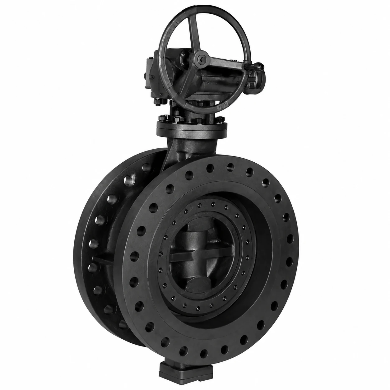
Most industrial water service applications specify the wafer pattern butterfly valve, where the valve body is sandwiched between two pipe flanges using the flange bolting that already connects the pipe joint. The wafer body is the lightest configuration and the most economical on a per-unit basis. Long stud bolts pass through both mating flanges and around the outside of the valve body, clamping the complete assembly together. The wafer design requires the downstream flange to be in place for the valve to seal — it cannot be used as an end-of-line valve.
Lug pattern butterfly valves have threaded metal inserts — lugs — cast or machined into the body at each bolt hole position. Each lug accepts a bolt independently from either side of the valve. This means one side of the pipeline can be disconnected and removed while the other side remains under pressure — useful where downstream equipment needs periodic removal for maintenance, or where the butterfly valve serves as a maintenance isolation point between two sections of a water distribution network. Lug valves can be used at the end of a line with a blind flange on the downstream side.
Flanged butterfly valves have integral raised-face flanges on the body that bolt directly to the mating pipe flanges. They are specified where the project piping specification mandates flanged connections, on larger diameters where wafer clamping through long stud bolts becomes impractical, or where the valve is installed at the end of an open line. Flanged butterfly valves are heavier and cost more than the equivalent wafer or lug configuration because of the additional body material in the flanges. The Wafer Butterfly Valves category covers wafer and lug butterfly valve configurations for project specification review.
Seat Material, Disc Material and Temperature Range
The seat is the primary sealing element in a butterfly valve, and the material choice determines media compatibility and the upper service temperature. EPDM is the default seat material for general water service — potable water, cooling water, chilled water, heating water, treated effluent and raw water. It provides good sealing with low operating torque and handles water temperatures from approximately minus 10 degrees C to plus 120 degrees C. EPDM is not suitable for hydrocarbon or oil service because the material swells and degrades on contact with petroleum-based fluids.
NBR, also referred to as nitrile or Buna-N, is specified where oil, hydrocarbon or fuel resistance is required alongside water resistance. On fire water ring mains where diesel fuel contamination from fire pump engine systems is possible, or on cooling water lines that carry trace oil carryover from process heat exchangers, NBR provides better chemical resistance than EPDM with a similar temperature range. The trade-off is slightly higher cost and slightly reduced elasticity compared to EPDM.
PTFE seats are selected for higher chemical resistance, higher temperature ranges up to approximately plus 180 degrees C, and applications where the seat must resist chemical attack — high-purity water systems, aggressive water treatment chemicals at dosing points, or process water with variable chemistry. PTFE seats cost more than elastomeric seats and require higher operating torque because the material is less elastic. The actuator or gear operator must be sized to overcome the higher seat torque, not just the bearing and packing friction.
The disc material follows the water quality, corrosion environment and project material specification. Ductile iron with a fused epoxy coating or nylon 11 coating is the standard for general water service — the coating isolates the iron substrate from the water and provides a smooth surface for seat sealing. Cast steel or stainless steel discs are specified where the water chemistry, temperature or the project piping specification requires a material upgrade. Confirm the disc material, coating type and coating thickness against the project valve data sheet. The seat and disc combination must be reviewed as a pair — the seat material must be compatible with the disc coating or base material at the maximum operating temperature.
Operation Mode
Manual lever operation covers butterfly valves up to approximately DN200 in general water and HVAC service. The lever provides direct quarter-turn operation from fully closed to fully open, and a notched position plate with 10-degree or 15-degree increments allows the operator to set and lock the disc at intermediate positions for flow balancing or commissioning. Lever-operated butterfly valves are the most economical configuration and the simplest to install — no power supply, no control wiring, no instrument air connection.
Gear operators are specified above DN200, or on any butterfly valve where closing against full differential pressure requires mechanical advantage that a direct lever cannot provide. A gear operator multiplies the handwheel input torque through a worm gear set with a typical ratio between 30:1 and 80:1 depending on valve size and pressure class. The self-locking characteristic of the worm gear set prevents the disc from drifting under flow forces — once the operator stops turning the handwheel, the disc holds its position. Gear operators are mandatory where the butterfly valve must hold position against flow without external locking, and they are the standard configuration for buried or below-grade valve installations where a lever would not have clearance to operate.
Electric actuators are common on butterfly valves integrated into building management systems, water treatment plant SCADA networks or remote pumping station control panels. The actuator receives an open-close or modulating signal from the control system and drives the valve through its 90-degree stroke. Actuator sizing must be based on the valve torque requirement — not simply the nominal valve size — because the required torque varies with seat material, pressure class and service conditions. The actuator enclosure rating must match the installation environment. For outdoor installations on cooling tower yards, pipe bridges or tank farm water mains, an IP67 or IP68 enclosure is commonly specified.
Pneumatic actuators with spring-return are used where fail-safe operation is required — for example, on cooling water supply to critical process equipment where loss of instrument air or control signal must drive the valve to a pre-determined safe position. The spring-return mechanism closes or opens the valve on loss of power, with the spring direction specified at the ordering stage. When specifying an actuated butterfly valve, confirm the power supply voltage and phase for electric actuators, the instrument air pressure range for pneumatic actuators, the control signal type and position feedback output, the fail position, and the enclosure or area classification rating for the installation location.
Inspection and Documentation
Butterfly valve orders for water and HVAC projects include a documentation package that confirms each valve matches the specification before shipment. The documentation is filed for commissioning records and retained for the operating life of the installation. A hydrostatic shell test report documents that the valve body withstood the test pressure — 1.5 times the rated pressure — for the required duration without visible leakage or permanent deformation. A seat leakage test report confirms that the closed disc and seat seal met the permissible leakage rate at the test pressure.
Material certificates to EN 10204 Type 3.1 or equivalent confirm the chemical composition and mechanical properties of the pressure-containing parts — body, disc and stem. For ductile iron bodies, the material certificate confirms the grade — EN-GJS-400-15, EN-GJS-400-18 or equivalent. For coated discs, the coating inspection record confirms the epoxy or nylon coating type, thickness in micrometres, adhesion test result and holiday test result where specified. Dimensional inspection records verify the face-to-face dimension, flange drilling, overall height and handwheel or actuator centreline height against the project valve data sheet and the applicable design standard.
For actuated butterfly valves, the actuator wiring diagram, torque setting certificate and function test record are included. The function test confirms that the actuator drives the valve through its full stroke without obstruction, that the limit switches signal correctly at both ends of travel, and that the position feedback matches the actual disc position. Honiks works with qualified partner factories to coordinate inspection and documentation for industrial water valve orders. See the Quality Control page for inspection management and the Factory Capability page for production and supply arrangements.
Buyer Inquiry Checklist
When preparing a butterfly valve RFQ for water, HVAC or fire water piping, include the following for each line item. Every field completed in the first submission reduces the number of clarification rounds before a quotation is returned.
- Valve type — wafer, lug or flanged butterfly valve
- DN or NPS size
- Pressure class — PN10, PN16, Class 125 or Class 150
- Body material — ductile iron, cast steel or stainless steel as specified
- Disc material — ductile iron with coating, cast steel or stainless steel
- Disc coating — epoxy or nylon where ductile iron is selected
- Seat material — EPDM, NBR or PTFE
- Stem material — stainless steel grade
- Flange standard — EN 1092 PN10/PN16, ASME B16.5 Class 125/150, AS 2129 or JIS as applicable
- Operation — lever, gear operator, electric actuator or pneumatic actuator
- If actuated — supply voltage and phase, control signal type, position feedback output, fail position, enclosure or area classification rating
- Medium — water type, maximum operating temperature, trace chemicals or treatment additives if any
- Quantity per type, size, pressure class and configuration
- Documentation requirements — test reports, material certificates, coating records, actuator documentation
A complete inquiry returns a proposal covering valve scope, material lead time and documentation plan in the first commercial response — reducing the back-and-forth that pushes the purchase order placement date further out.
Frequently Asked Questions
When should I choose a butterfly valve over a gate valve for water service?
Choose a butterfly valve when installation space is tight, the line diameter is DN300 or larger and weight is a practical consideration, quarter-turn operation suits the operating sequence, or the line does not require full-bore pigging capability. Choose a gate valve when full-bore flow with zero internal obstruction is required, the line must be piggable, or the piping specification mandates a gate valve for that service class. Above DN400, request a budget comparison for both types — the cost difference may influence the valve schedule.
What seat material should I choose for cooling water and chilled water?
EPDM is the standard seat material for clean cooling water, condenser water and chilled water — it provides reliable sealing across the typical operating temperature range and has a long service history in HVAC and industrial water applications. If the cooling water carries trace oil or hydrocarbon from process heat exchanger leakage, NBR may be a more suitable choice because of its oil resistance. Confirm the water chemistry and maximum temperature from the project heat balance or water treatment specification.
Is a butterfly valve acceptable for fire water mains?
A butterfly valve is used on industrial fire water ring mains, hydrant supply headers and fire pump isolation where the function is water distribution and sectional control. It is an industrial water distribution valve, not a listed fire protection device. If the project specification requires fire protection equipment that is listed by a testing laboratory or certified to a fire protection standard, the buyer must confirm those requirements independently — a butterfly valve selected for general industrial water service does not automatically meet such requirements.
Can a butterfly valve be used for throttling or flow balancing?
A butterfly valve can be positioned at an intermediate angle for flow modulation or commissioning flow balancing. The notched position plate on a lever-operated valve or the position feedback on an actuated valve allows repeatable setting at a specific disc angle. Prolonged throttling near the closed position — below approximately 20 degrees open — creates high-velocity flow across the disc edge and seat contact area, which accelerates seat wear. If the valve will operate at small openings for extended periods, confirm the seat material durability and expected service interval with the supplier or project engineer.
What prevents the butterfly valve disc from moving when the valve is in an intermediate position?
Gear operators are self-locking — the worm gear set cannot be back-driven by flow forces acting on the disc, so the disc holds its position without any external locking device. For lever-operated butterfly valves, the notched position plate with a spring-loaded locking pawl holds the lever at the set position. Electric actuators include an internal motor brake or self-locking gear train that prevents disc movement when the motor is de-energised. In all three cases, the holding mechanism is inherent to the operator — no separate locking pin, chain or padlock is required.
Send Your Butterfly Valve Requirements
Butterfly valve selection for water, HVAC and fire water piping starts with the pipe size, pressure class, medium data and seat material specification. A well-prepared inquiry checklist — with the line size, flange standard, pressure rating, medium, temperature range, seat material preference and operation mode clearly stated for each line item — enables a quotation that addresses the project conditions rather than a generic butterfly valve listing.
Contact Honiks with your valve list, data sheet and project specification for review and quotation.