Product Overview
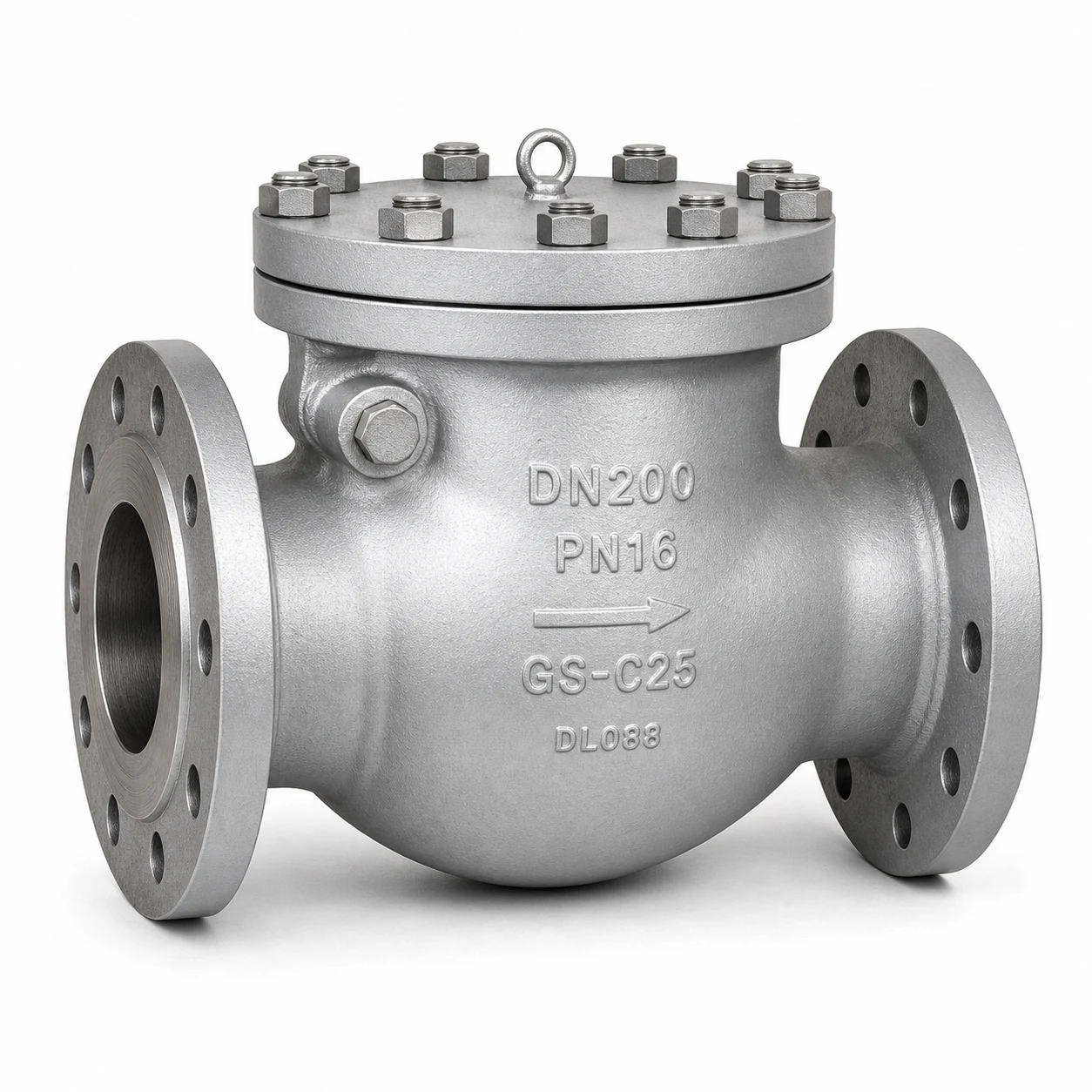
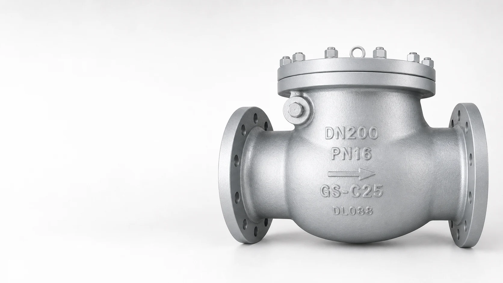
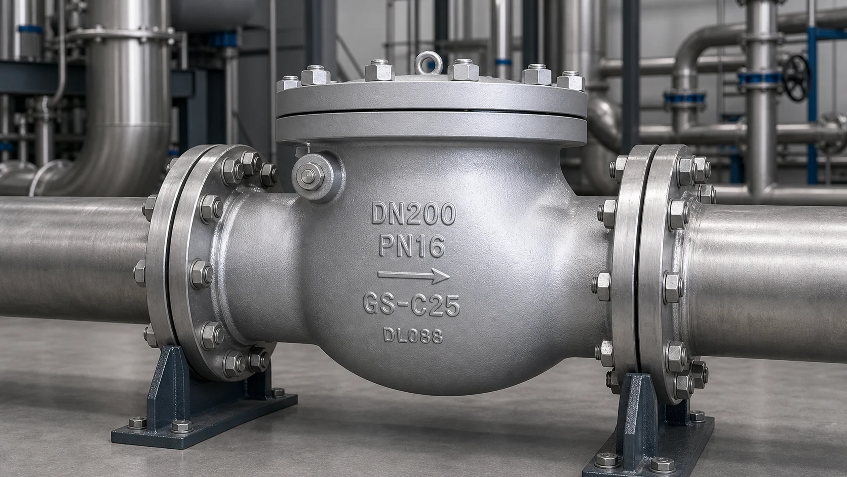
The HN67 Swing Check Valve is an EN/DIN self-acting non-return valve designed to help prevent reverse flow in horizontal pipeline systems. It is suitable for water, steam, air, gas and compatible industrial media.
The swing disc opens under forward flow and closes when reverse flow occurs. This design is commonly used in power engineering, chemical plants, petrochemical facilities, utility systems and general industrial pipelines where reliable reverse-flow protection is required.
HN67 is available from DN50 to DN600 with PN16, PN25 and PN40 pressure ratings. Connection options include EN 1092-1 flanged ends and project-dependent butt-welded ends, with body material options including carbon steel, alloy steel and stainless steel according to service conditions.
Key Features
- Swing check design for self-acting reverse-flow prevention.
- Bolted bonnet cap construction for maintenance access.
- Anti-rotation disc arrangement and renewable seat ring.
- Non-penetrating disc shaft design according to catalog construction.
- Disc can open fully with a small pressure differential under suitable service conditions.
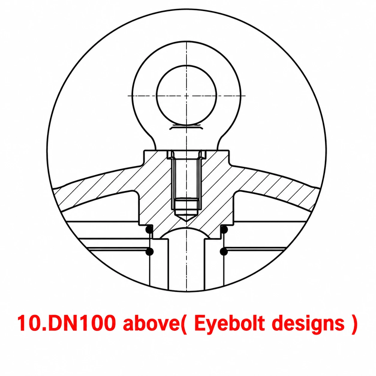
- DN100 and above can use eyebolt design for lifting and handling.
- Flanged and butt-welded connection options for EN/DIN pipeline projects.
Sectional Structure and Materials
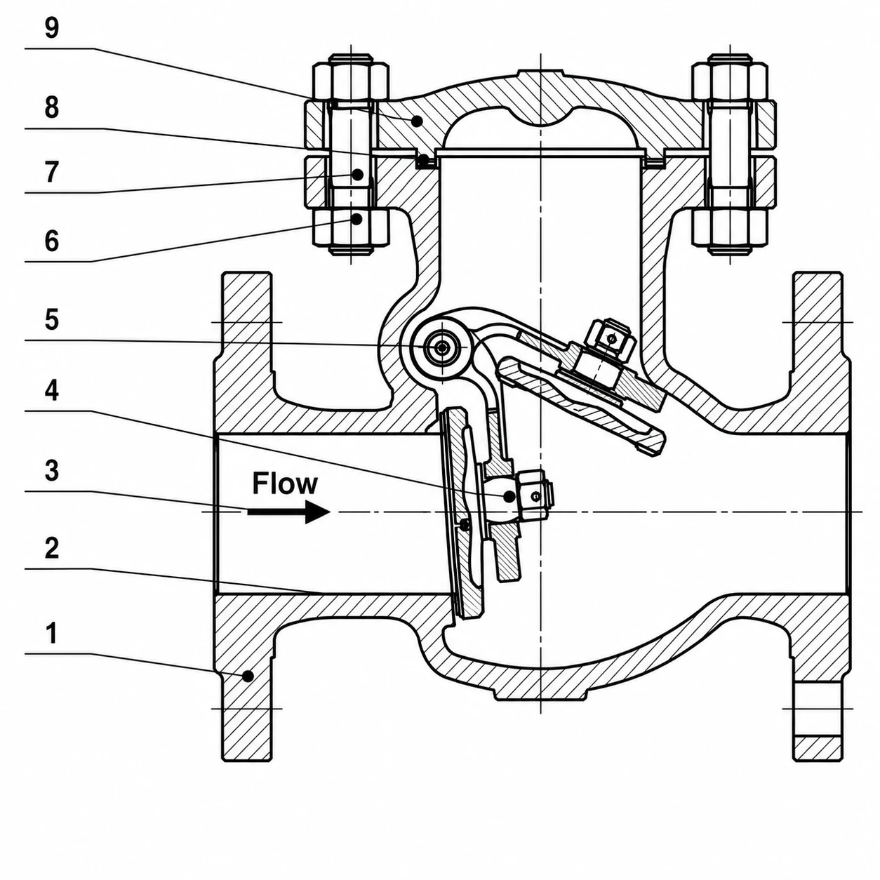
The numbered sectional drawing corresponds to the position numbers in the materials table. Final material selection should be confirmed according to pressure rating, temperature and fluid compatibility.
| Pos. | Name | Typical Material Options |
|---|---|---|
| 1 | Body | 1.0619 / A216 WCB; 1.7357 / A217 WC6; 1.4408 / A351 CF8M |
| 2 | Seat | 13Cr, STL or project-specified equivalent |
| 3 | Disc | 1.0619 / A216 WCB; 1.7357 / A217 WC6; 1.4408 / A351 CF8M |
| 4 | Disc nut | Carbon steel, SS316 or project-specified equivalent |
| 5 | Arm | 1.0619 / A216 WCB; 1.7357 / A217 WC6; 1.4408 / A351 CF8M |
| 6 | Nut | ASTM A194 2H, A194 4, A194 8M or equivalent |
| 7 | Bolt | ASTM A193 B7, A193 B16, A193 B8M or equivalent |
| 8 | Gasket | Graphite + SS304 or SS316 |
| 9 | Bonnet | 1.0619 / A216 WCB; 1.7357 / A217 WC6; 1.4408 / A351 CF8M |
| 10 | Eyebolt | Carbon steel |
Typical materials are listed for preliminary selection. Other material combinations may be discussed according to actual service conditions.
Eyebolt Design Detail
For DN100 and above, the catalog shows an eyebolt design detail for lifting and handling. Final lifting arrangement should be confirmed against approved drawings and project requirements.
Technical Specifications
| Product Type | Swing Check Valve |
|---|---|
| Model | HN67 |
| Nominal Size | DN50-DN600 |
| Pressure Rating | PN16, PN25, PN40 |
| Connection Types | EN 1092-1 flanged ends; butt-welded ends by project request |
| Face-to-Face | EN 558-1; DIN 3202 F1 / F6 series |
| Butt-Welded Ends | EN 12627 |
| Body Materials | Carbon steel, alloy steel, stainless steel options |
| Operation | Self-acting by line pressure |
| Installation | Horizontal pipeline installation recommended |
| Temperature Range | Material and pressure rating dependent |
Dimensions and Performance Data
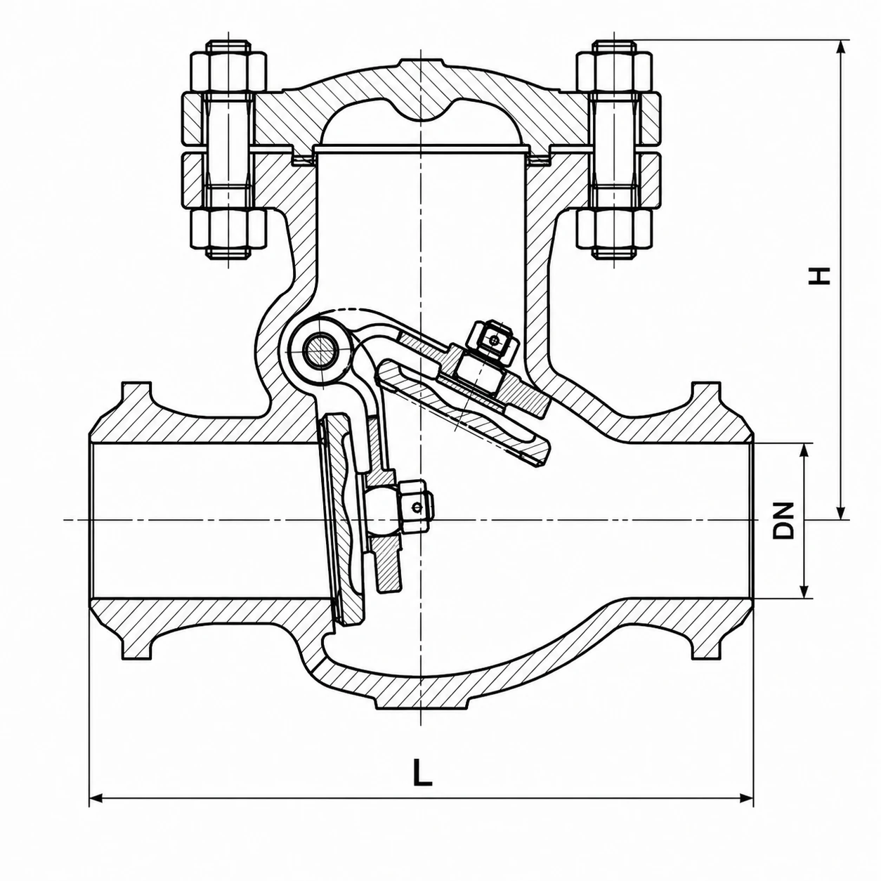
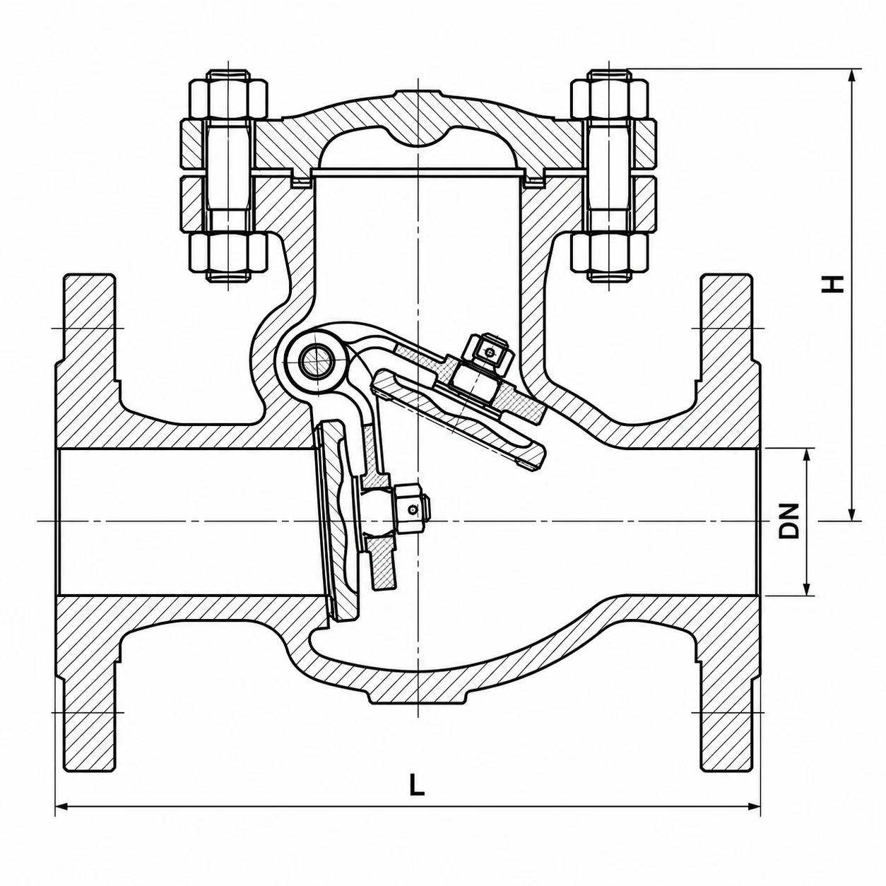
The drawings show the corresponding dimensional symbols used in the table below. Values are for preliminary selection and should be confirmed against approved drawings before order.
| DN | 50 | 65 | 80 | 100 | 125 | 150 | 200 | 250 | 300 | 350 | 400 | 450 | 500 | 600 |
|---|---|---|---|---|---|---|---|---|---|---|---|---|---|---|
| L, mm For F6 | 200 | 240 | 260 | 300 | 350 | 400 | 500 | 600 | 700 | 800 | 900 | 1000 | 1100 | 1300 |
| L, mm For F1 | 230 | 290 | 310 | 350 | 400 | 480 | 600 | 730 | 850 | 980 | 1100 | 1200 | 1250 | 1450 |
| H, mm For F6 | 147 | 161 | 178 | 190 | 265 | 285 | 345 | 395 | 420 | 455 | 520 | 565 | 610 | 740 |
| H, mm For F1 | 152 | 178 | 185 | 210 | 290 | 310 | 365 | 445 | 480 | 510 | 545 | 595 | 655 | 860 |
| Weight FL F1 PN16, kg | 17 | 25 | 32 | 37 | 52 | 76 | 120 | 210 | 320 | 420 | 640 | 950 | 1050 | 1300 |
| Weight FL F1 PN25, kg | 18 | 28 | 42 | 62 | 83 | 137 | 220 | 310 | 400 | 545 | 730 | 1050 | 1180 | 1400 |
| Weight FL F1 PN40, kg | 18 | 28 | 42 | 62 | 83 | 137 | 230 | 330 | 440 | 595 | 785 | 1100 | 1250 | 1550 |
| Weight BW F1 PN16, kg | 10 | 17 | 22 | 25 | 35 | 54 | 86 | 155 | 240 | 300 | 500 | 620 | 850 | 950 |
| Weight BW F1 PN25, kg | 10 | 19 | 30 | 45 | 60 | 105 | 180 | 240 | 285 | 350 | 540 | 680 | 720 | 850 |
| Weight BW F1 PN40, kg | 10 | 19 | 30 | 45 | 60 | 105 | 180 | 240 | 285 | 350 | 540 | 680 | 720 | 850 |
Pressure-Temperature Reference
The maximum allowable working pressure varies with operating temperature and material grade. The following table is catalog reference data based on EN 12516-1.
| Material | PN | 100 | 150 | 200 | 250 | 300 | 350 | 400 | 425 | 450 | 500 | 525 | 550 | 575 | 595 |
|---|---|---|---|---|---|---|---|---|---|---|---|---|---|---|---|
| 1.0619 / A216 WCB | 16 | 1.36 | 1.27 | 1.14 | 1.04 | 0.94 | 0.88 | 0.84 | – | – | – | – | – | – | – |
| 1.0619 / A216 WCB | 25 | 2.13 | 1.98 | 1.78 | 1.62 | 1.47 | 1.37 | 1.32 | – | – | – | – | – | – | – |
| 1.0619 / A216 WCB | 40 | 3.41 | 3.17 | 2.84 | 2.60 | 2.35 | 2.19 | 2.11 | – | – | – | – | – | – | – |
| 1.4408 / A351 CF8M | 16 | 1.33 | 1.20 | 1.10 | 1.02 | 0.96 | 0.91 | 0.87 | 0.86 | 0.86 | 0.83 | – | – | – | – |
| 1.4408 / A351 CF8M | 25 | 2.07 | 1.87 | 1.72 | 1.60 | 1.50 | 1.42 | 1.36 | 1.35 | 1.34 | 1.30 | – | – | – | – |
| 1.4408 / A351 CF8M | 40 | 3.32 | 2.99 | 2.75 | 2.56 | 2.41 | 2.27 | 2.18 | 2.16 | 2.14 | 2.08 | – | – | – | – |
| 1.7357 / A217 WC6 | 16 | 1.63 | 1.58 | 1.49 | 1.43 | 1.33 | 1.23 | 1.15 | 1.11 | 1.07 | 0.89 | 0.68 | 0.35 | 0.28 | 0.20 |
| 1.7357 / A217 WC6 | 25 | 2.54 | 2.48 | 2.33 | 2.23 | 2.08 | 1.93 | 1.80 | 1.73 | 1.67 | 1.39 | 1.06 | 0.55 | 0.43 | 0.32 |
| 1.7357 / A217 WC6 | 40 | 4.07 | 3.96 | 3.74 | 3.57 | 3.33 | 3.09 | 2.89 | 2.77 | 2.67 | 2.23 | 1.70 | 0.88 | 0.69 | 0.52 |
Temperature values not listed in the table should be selected by linear interpolation method or confirmed during project review.
Applications
- Water, steam, air and gas pipelines requiring self-acting reverse-flow prevention.
- Power engineering auxiliary systems and plant utility lines.
- Chemical and petrochemical pipelines where reverse flow should be controlled.
- Pump discharge lines and process systems requiring non-return service.
- General industrial pipelines using EN/DIN flanged or butt-welded connections.
Testing, Installation and Operation
Testing
- Pressure tested by water for strength and tightness according to EN 12266.
- Strength test pressure: minimum 1.5 x nominal pressure.
- Certification and documentation can be discussed according to project requirements.
Installation
- Horizontal pipeline installation is recommended for this swing check valve.
- Flow direction should follow the body mark.
Operation
- Self-acting by pressure of medium.
- Rocker and hinge pin can use an inside-set design according to catalog construction.
Standards and Compliance
- Flanged connections: EN 1092-1
- Butt-welded ends: EN 12627
- Face-to-face dimensions: EN 558-1; DIN 3202 F1 / F6 series
- Pressure testing: EN 12266
- Material selection: project and service-condition dependent
Typical specifications are listed above. Actual configurations vary by supplier, material grade and project requirements. Contact Honiks with your working conditions for detailed quotation support.
FAQ
Q: What is the difference between HN67 and HN65?
A: HN67 is a swing check valve, while HN65 is a lift check valve. HN67 uses a hinged swing disc and is commonly selected for horizontal non-return pipeline service.
Q: Which direction should the valve be installed?
A: The valve should be installed according to the flow direction marked on the body. Horizontal installation is recommended for this swing check construction.
Q: Does HN67 require manual operation?
A: No. HN67 is self-acting. The disc opens under forward flow and closes when reverse flow occurs.
Q: What connection options are available?
A: HN67 can be supplied with EN 1092-1 flanged ends or project-dependent butt-welded ends.
Q: Why is an eyebolt detail shown?
A: The catalog shows an eyebolt design detail for DN100 and above. Final lifting details should be confirmed during drawing approval.

Reviews
There are no reviews yet.