Product Overview
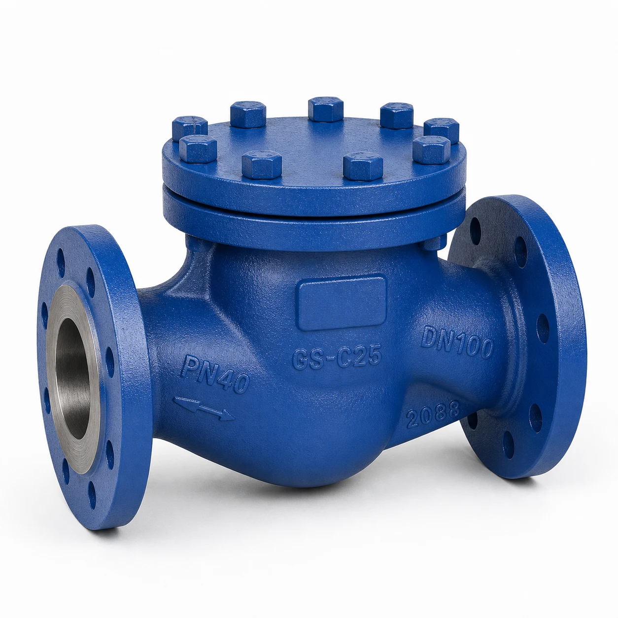
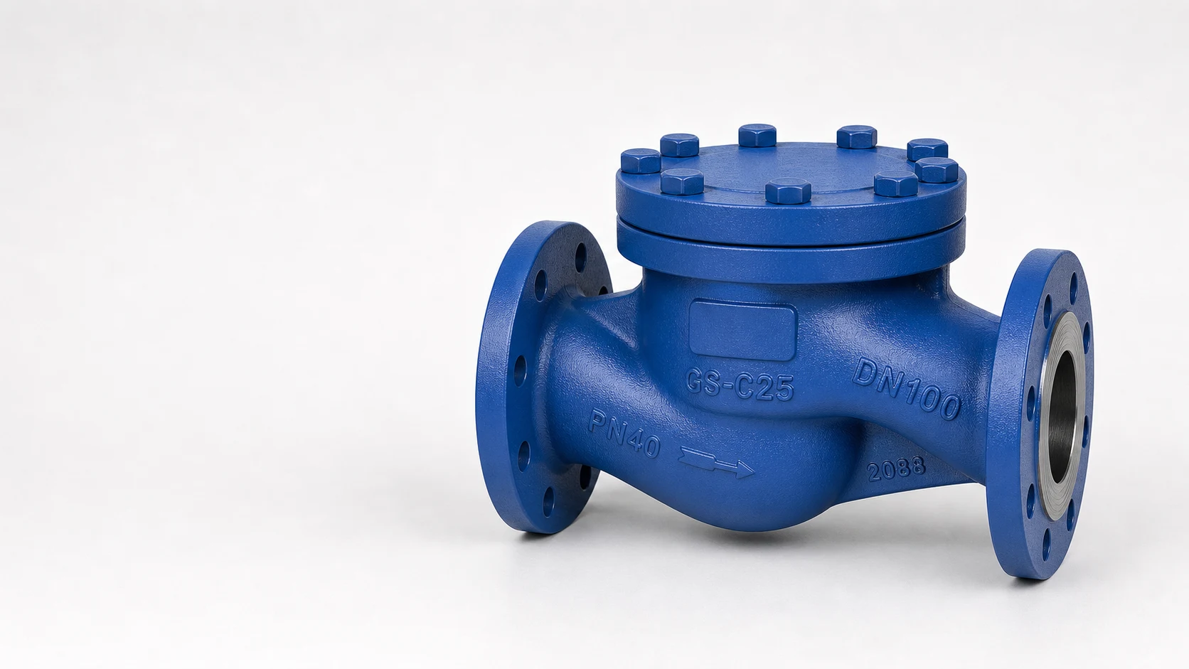
The HN65 Lift Check Valve is an EN/DIN industrial non-return valve designed for self-acting reverse-flow prevention. The valve disc opens under forward flow pressure and closes when reverse flow or back pressure occurs, helping protect pumps, pipelines and process equipment.
HN65 is available from DN15 to DN400 with PN16, PN25 and PN40 pressure ratings. Connection options include EN 1092-1 flanged ends and project-dependent butt-welded ends. The valve is normally installed in horizontal pipelines, with flow direction confirmed according to the body mark and approved drawing.
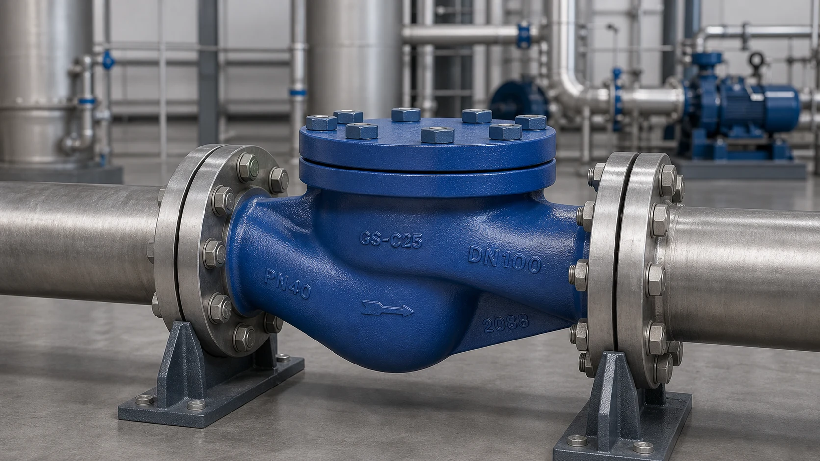
Typical applications include water, steam, air, gas, power engineering, chemical processing and petrochemical pipeline systems. Final material and configuration selection should be confirmed according to pressure rating, temperature and fluid compatibility.
Key Features
- Self-acting lift check design for non-return service.
- Disc closes by reverse flow or pressure change, without manual operation.
- Suitable for horizontal pipeline installation.
- DN15-DN400 size range with PN16, PN25 and PN40 pressure ratings.
- Flanged and butt-welded connection options according to project requirement.
- Compact bolted cover construction for industrial service.
- Suitable for water, steam, air, gas and compatible industrial fluids.
Sectional Structure and Materials
The numbered sectional drawing corresponds to the position numbers in the materials table. HN65 uses 7 numbered material positions.
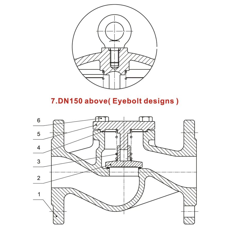
| Pos. | Name | Material |
|---|---|---|
| 1 | Body | 1.0619 / A216 WCB; 1.7357 / A217 WC6; 1.4408 / A351 CF8M |
| 2 | Seat | 13Cr, STL |
| 3 | Stem | Graphite + SS304, SS316 |
| 4 | Gasket | SS304, SS316 |
| 5 | Bonnet | 1.0619 / A216 WCB; 1.7357 / A217 WC6; 1.4408 / A351 CF8M |
| 6 | Bolt | ASTM A193 B7, A193 B16, A193 B8M |
| 7 | Eyebolt | Carbon steel |
Technical Specifications
| Valve type | Lift check valve |
|---|---|
| Standard range | EN/DIN industrial valve |
| Nominal size | DN15-DN400 |
| Pressure rating | PN16, PN25, PN40 |
| Body materials | A216 WCB, A217 WC6, A351 CF8M or project-specified equivalent |
| Connection options | Flanged EN 1092-1, butt-welded EN 12627 or project-specified connection |
| Face-to-face | EN 558-1 / DIN 3202 F1 Series reference |
| Operation | Self-acting by pressure of medium |
| Installation | Horizontal pipeline installation |
| Typical service | Non-return / reverse-flow prevention service |
Dimensions and Performance Data
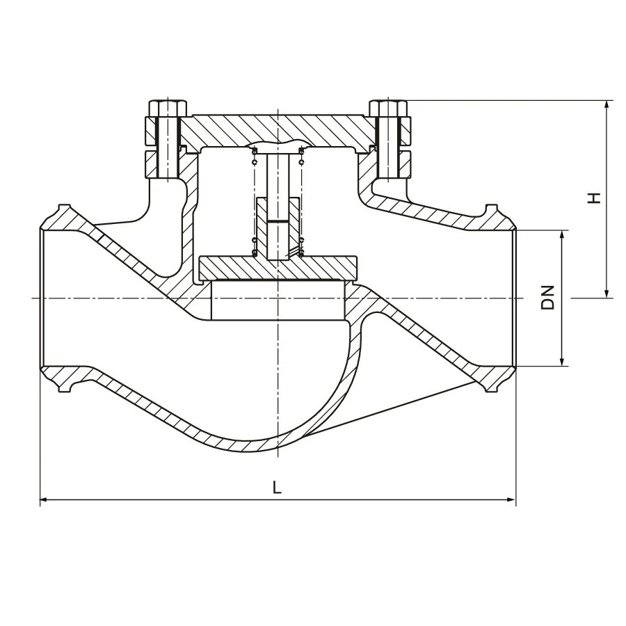
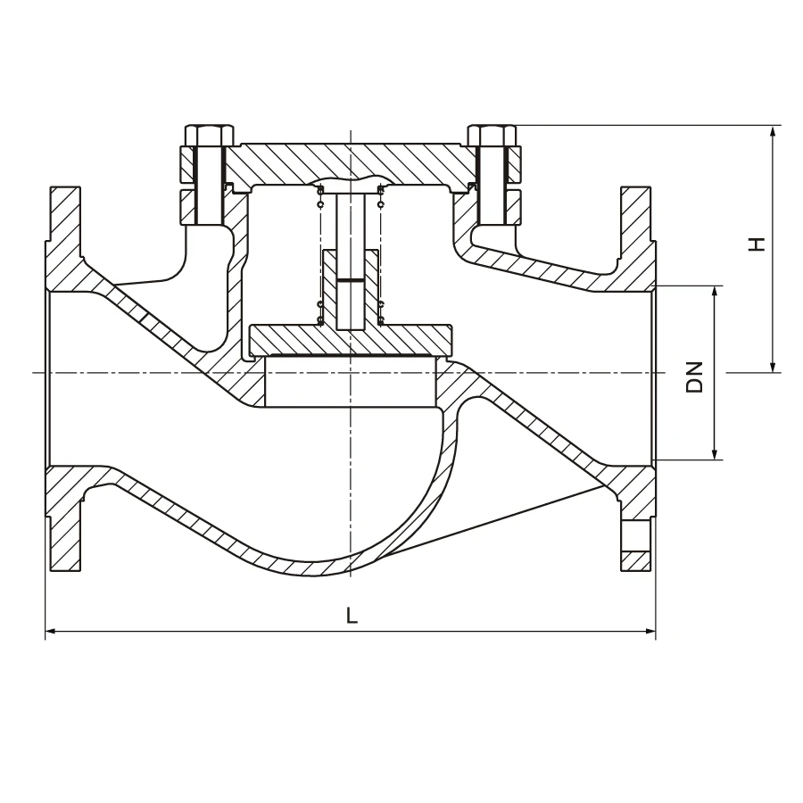
The drawings show dimensional symbols used in the table below. Values are for preliminary selection and should be confirmed against the approved datasheet before order.
| Parameter | DN15 | DN20 | DN25 | DN32 | DN40 | DN50 | DN65 | DN80 | DN100 | DN125 | DN150 | DN200 | DN250 | DN300 | DN350 | DN400 |
|---|---|---|---|---|---|---|---|---|---|---|---|---|---|---|---|---|
| L mm | 130 | 150 | 160 | 180 | 200 | 230 | 290 | 310 | 350 | 400 | 480 | 600 | 730 | 850 | 980 | 1100 |
| H mm | 69 | 70 | 75 | 78 | 85 | 90 | 110 | 125 | 150 | 185 | 285 | 340 | 400 | 445 | 490 | 595 |
| Weight FL PN16 kg | 2.8 | 3.5 | 4.2 | 5.5 | 7.5 | 9.4 | 13 | 17.5 | 29.2 | 40 | 60 | 116 | 220 | 330 | 520 | 820 |
| Weight FL PN25 kg | 2.8 | 3.5 | 4.2 | 5.5 | 7.5 | 9.5 | 14 | 20 | 32.5 | 48 | 73 | 128 | 210 | 350 | 560 | 850 |
| Weight FL PN40 kg | 2.8 | 3.5 | 4.2 | 5.5 | 7.5 | 9.5 | 14 | 20 | 32.5 | 48 | 73 | 136.5 | 288.5 | 390 | 610 | 920 |
| Weight BW PN16 kg | 1.9 | 2.2 | 2.8 | 3.5 | 4.6 | 5.1 | 8.4 | 14 | 22.5 | 36 | 51 | 108 | 203 | 308 | 210 | 560 |
| Weight BW PN25 kg | 1.9 | 2.2 | 2.8 | 3.5 | 4.6 | 5.1 | 8.4 | 14 | 23 | 38 | 53 | 110 | 223 | 315 | 300 | 580 |
| Weight BW PN40 kg | 1.9 | 2.2 | 2.8 | 3.5 | 4.6 | 5.1 | 8.4 | 14 | 23 | 38 | 53 | 110 | 223 | 315 | 400 | 600 |
| Kv | 3.9 | 6.9 | 11.1 | 17.6 | 27.8 | 43.5 | 71.3 | 112 | 174 | 267 | 380 | 670 | 1060 | 1514 | 2060 | 2690 |
Pressure-Temperature Reference
Working pressure varies by material grade and operating temperature. The following EN 12516-1 reference values are listed in MPa for preliminary selection only. For project conditions, confirm allowable pressure-temperature values against the approved material standard and project datasheet.
| Material | PN | 100°C | 150°C | 200°C | 250°C | 300°C | 350°C | 400°C | 425°C | 450°C | 500°C | 525°C | 550°C | 575°C | 595°C |
|---|---|---|---|---|---|---|---|---|---|---|---|---|---|---|---|
| 1.0619 / A216 WCB | PN16 | 1.36 | 1.27 | 1.14 | 1.04 | 0.94 | 0.88 | 0.84 | – | – | – | – | – | – | – |
| 1.0619 / A216 WCB | PN25 | 2.13 | 1.98 | 1.78 | 1.62 | 1.47 | 1.37 | 1.32 | – | – | – | – | – | – | – |
| 1.0619 / A216 WCB | PN40 | 3.41 | 3.17 | 2.84 | 2.60 | 2.35 | 2.19 | 2.11 | – | – | – | – | – | – | – |
| 1.4408 / A351 CF8M | PN16 | 1.33 | 1.20 | 1.10 | 1.02 | 0.96 | 0.91 | 0.87 | 0.86 | 0.86 | 0.83 | – | – | – | – |
| 1.4408 / A351 CF8M | PN25 | 2.07 | 1.87 | 1.72 | 1.60 | 1.50 | 1.42 | 1.36 | 1.35 | 1.34 | 1.30 | – | – | – | – |
| 1.4408 / A351 CF8M | PN40 | 3.32 | 2.99 | 2.75 | 2.56 | 2.41 | 2.27 | 2.18 | 2.16 | 2.14 | 2.08 | – | – | – | – |
| 1.7357 / A217 WC6 | PN16 | 1.63 | 1.58 | 1.49 | 1.43 | 1.33 | 1.23 | 1.15 | 1.11 | 1.07 | 0.89 | 0.68 | 0.35 | 0.28 | 0.20 |
| 1.7357 / A217 WC6 | PN25 | 2.54 | 2.48 | 2.33 | 2.23 | 2.08 | 1.93 | 1.80 | 1.73 | 1.67 | 1.39 | 1.06 | 0.55 | 0.43 | 0.32 |
| 1.7357 / A217 WC6 | PN40 | 4.07 | 3.96 | 3.74 | 3.57 | 3.33 | 3.09 | 2.89 | 2.77 | 2.67 | 2.23 | 1.70 | 0.88 | 0.69 | 0.52 |
Applications
- Water, steam, air and gas service.
- Power engineering pipeline systems.
- Chemical and petrochemical industry service.
- Pump discharge lines where reverse-flow prevention is required.
- General industrial pipelines requiring self-acting non-return protection.
Testing, Installation and Operation
Testing
- Pressure tests are carried out according to EN 12266.
- Strength test pressure is 1.5 x PN.
- Certification and inspection records can be discussed according to order requirements.
Installation
- Lift check valve installation should be horizontal.
- Flow direction should follow the body mark and approved drawing.
Operation
- Self-acting operation by pressure of medium.
- No manual handwheel operation is required.
Standards and Compliance
- Pressure testing: EN 12266.
- Flange connection: EN 1092-1 or customer request.
- Butt-welded connection: EN 12627.
- Face-to-face dimension: EN 558-1 / DIN 3202 F1 Series reference.
- Pressure-temperature reference: EN 12516-1.
Frequently Asked Questions
What is HN65 used for?
HN65 is used for non-return service in horizontal pipelines, helping prevent reverse flow in water, steam, air, gas and compatible industrial fluid systems.
How does a lift check valve work?
Forward flow lifts the valve disc from the seat. When flow stops or reverses, the disc returns to the seat by pressure change and gravity, helping block reverse flow.
Can HN65 be installed vertically?
The catalog installation note specifies horizontal installation. Final installation orientation should follow the approved drawing and project requirements.
What is the size and pressure range?
The catalog range is DN15-DN400 with PN16, PN25 and PN40 pressure ratings.
Need a quote for HN65 lift check valves? Contact us with your DN, PN and material requirements.
Reviews
There are no reviews yet.