Product Overview
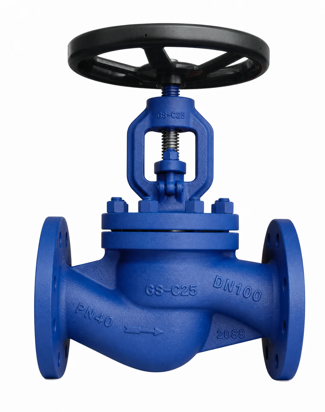
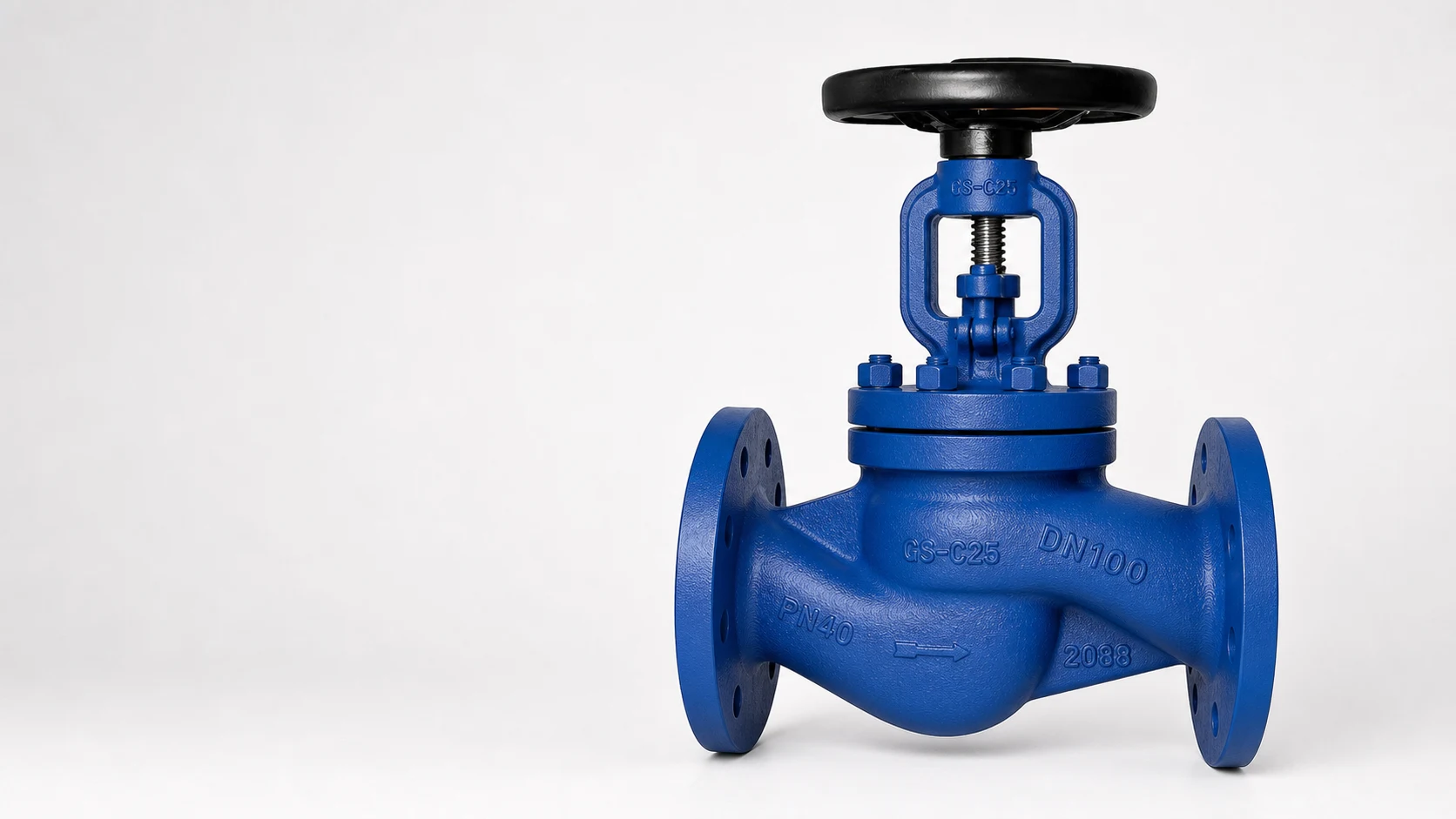
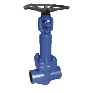
The HN61 Globe Valve is an EN/DIN industrial globe valve designed for shut-off and flow regulation service in industrial pipeline systems. Its linear-motion disc and seat design makes it suitable for applications where controlled opening, throttling or reliable shut-off is required.
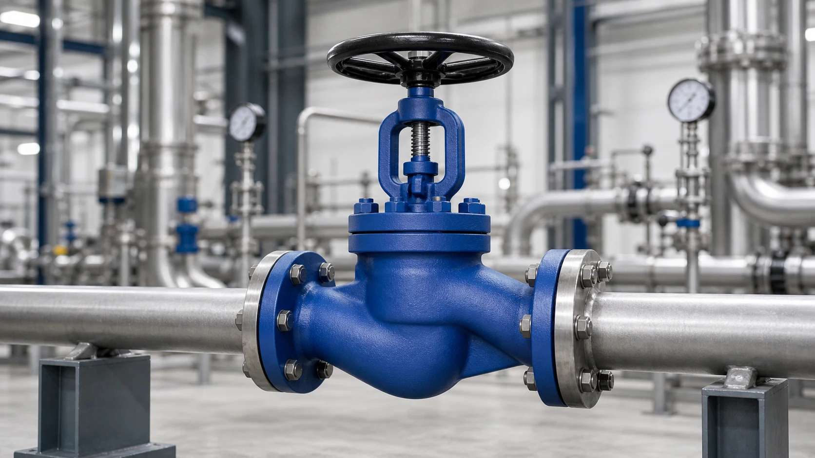
HN61 can be used for water, steam, air, oil, gas and selected compatible industrial media. Typical applications include power engineering, chemical processing, petrochemical pipelines, utility systems, boiler auxiliary lines and general industrial process pipelines.
The series is available from DN15 to DN400, with PN16, PN25 and PN40 pressure ratings. Connection options include EN 1092-1 flanged ends and project-dependent butt-welded ends. Final configuration should be confirmed according to pressure rating, temperature, medium and project requirements.
Key Features
- Globe valve flow path: Designed for shut-off and selected throttling service when specified for the operating conditions.
- Rising rotating stem: Source catalog describes a rotating, rising stem construction.
- Gradual opening: Helps reduce hydraulic and thermal shock risk during operation.
- EN/DIN pipeline compatibility: Suitable for DN and PN rated European industrial pipeline projects.
- Flanged or butt-welded ends: Connection options can be selected according to installation requirements.
- Project-based disc options: Throttling plug and larger-size disc configurations may be discussed for specific flow control requirements.
Applications and Technical Description
Applications
- Closing or throttling liquid and gaseous media.
- Water, steam, air, crude petroleum and petroleum products.
- Natural gas, gas condensate, technological solutions, oxygen, liquid and non-aggressive gases.
- Power engineering, chemical and petrochemical industry.
Technical Description
- Stem is rotating and rising.
- Valve opening is provided slowly, with gradual suspension of the stroke.
- Shut-off valves can be operated in open-close position; throttling operation may be selected for intermediate positions when properly specified.
Sectional Structure and Materials
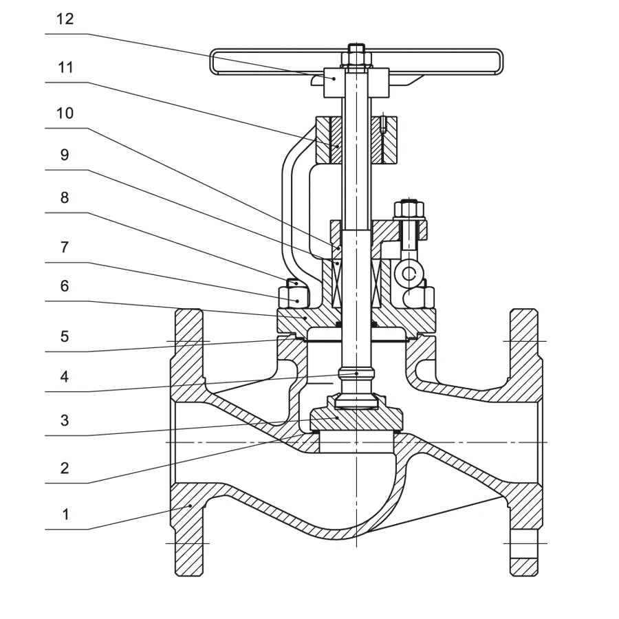
The numbered sectional drawing corresponds to the position numbers in the materials table. HN61 uses 12 numbered material positions. Final material selection should be confirmed according to pressure rating, temperature and fluid compatibility.
| Pos. | Name | Material |
|---|---|---|
| 1 | Body | 1.0619 (A216 WCB), 1.7357 (A217 WC6), 1.4408 (A351 CF8M) |
| 2 | Seat | 13Cr, STL6 |
| 3 | Disc | A105, F316 |
| 4 | Stem | X20Cr13, F316 |
| 5 | Gasket | Graphite + stainless steel |
| 6 | Bonnet | 1.0619 (A216 WCB), 1.7357 (A217 WC6), 1.4408 (A351 CF8M) |
| 7 | Bolt | A193 B7, A193 B16, A193 B8M |
| 8 | Nut | A194 2H, A194 4, A194 8M |
| 9 | Packing | Graphite |
| 10 | Gland | 1.0619 (A216 WCB), 1.7357 (A217 WC6), 1.4408 (A351 CF8M) |
| 11 | Stem nut | GGG40.3, Cu alloy |
| 12 | Handwheel | C.S |
Note: HN61 has 12 material positions in the source drawing.
Technical Specifications
| Parameter | Specification |
|---|---|
| Product Type | Globe valve |
| Honiks Model | HN61 |
| Standard Series | EN/DIN |
| Nominal Size | DN15-DN400 |
| Pressure Rating | PN16, PN25, PN40 |
| Connection Types | Flanged, butt-welded |
| Flange Standard | EN 1092-1 or project requirement |
| Face-to-Face | EN 558-1 |
| Testing | EN 12266-1; strength test minimum pressure 1.5 x PN |
| Operation | Handwheel, gearbox or electric actuator options |
| Temperature Range | Material and pressure rating dependent |
Dimensions and Performance Data
The drawings show dimensional symbols such as DN, L, H and Stroke. The table below provides reference dimensions, weights and Kv values for preliminary selection.
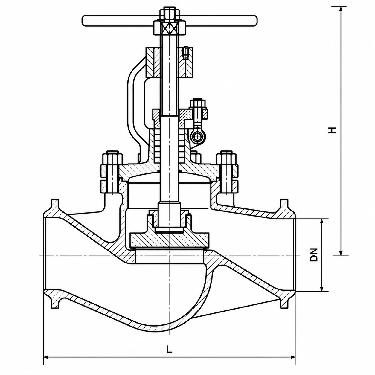
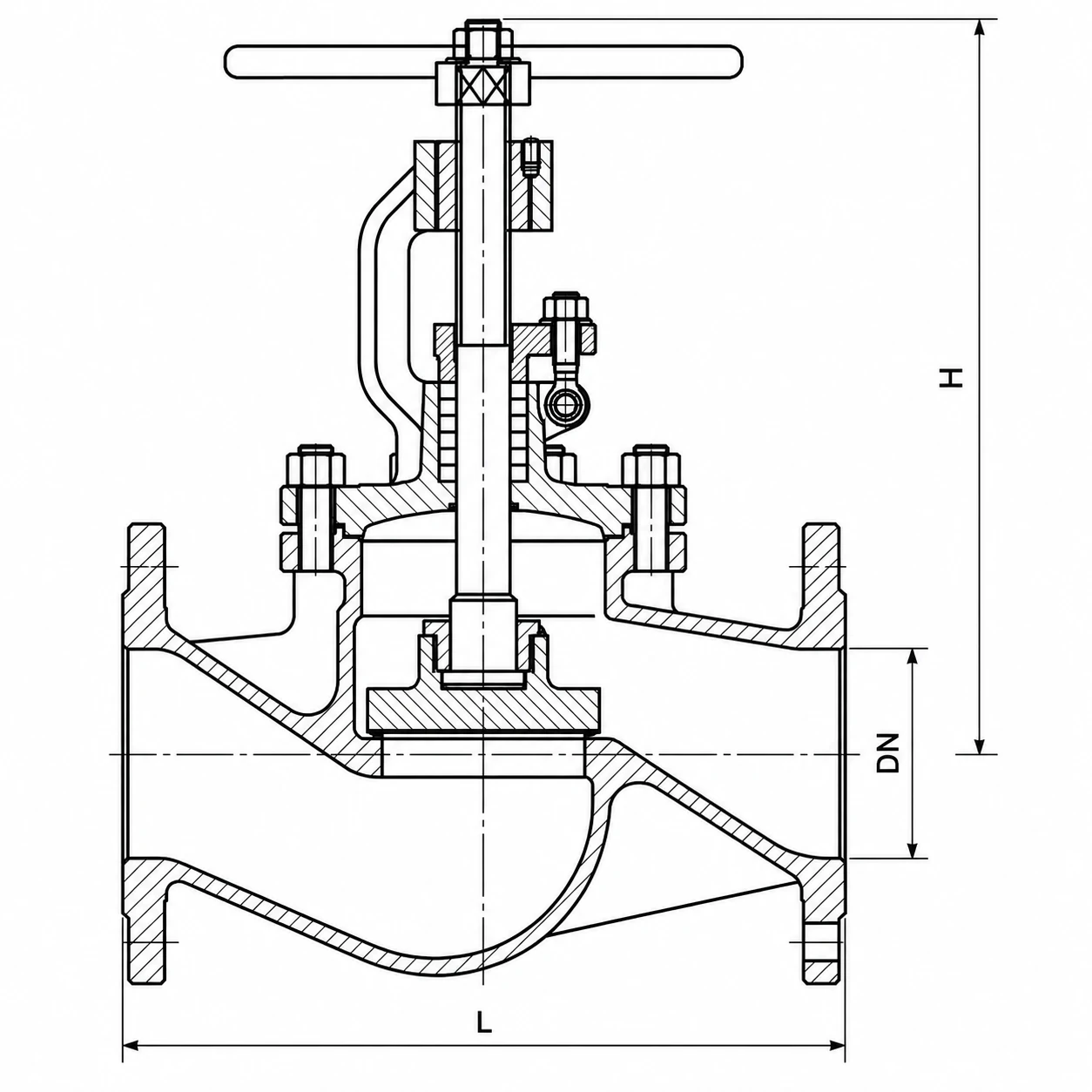
| DN | 15 | 20 | 25 | 32 | 40 | 50 | 65 | 80 | 100 | 125 | 150 | 200 | 250 | 300 | 350 | 400 |
|---|---|---|---|---|---|---|---|---|---|---|---|---|---|---|---|---|
| L, mm | 130 | 150 | 160 | 180 | 200 | 230 | 290 | 310 | 350 | 400 | 480 | 600 | 730 | 850 | 980 | 1100 |
| H, mm | 69 | 70 | 75 | 78 | 85 | 90 | 110 | 125 | 150 | 185 | 285 | 340 | 400 | 445 | 490 | 595 |
| Stroke, mm | 12 | 13 | 16 | 18 | 23 | 26 | 28 | 33 | 37 | 51 | 60 | 65 | 93 | 110 | 120 | 150 |
| Weight (kg) – Flanged Ends | ||||||||||||||||
| PN16 | 3.8 | 4.5 | 5.5 | 7.1 | 9.5 | 11.5 | 19.2 | 25.2 | 34.2 | 53.1 | 75.5 | 151.2 | 305 | 410 | 580 | 820 |
| PN25 | 3.8 | 4.5 | 5.5 | 7.1 | 9.5 | 12 | 20.2 | 27.2 | 38.2 | 59.5 | 86.5 | 159.5 | 310 | 438 | 640 | 865 |
| PN40 | 3.8 | 4.5 | 5.5 | 7.1 | 9.5 | 12 | 20.2 | 27.2 | 38.2 | 59.5 | 86.5 | 163.4 | 323 | 453 | 680 | 850 |
| Weight (kg) – Butt-Welded Ends | ||||||||||||||||
| PN16 | 2.2 | 2.7 | 3.5 | 3.8 | 5.4 | 6.8 | 13.4 | 19.2 | 28.2 | 45 | 67.5 | 105.5 | 228 | 316 | 415 | 595 |
| PN25 | 2.2 | 2.7 | 3.5 | 3.8 | 5.4 | 6.8 | 14.2 | 19.8 | 29.5 | 47.5 | 69.5 | 110.5 | 235 | 330 | 440 | 610 |
| PN40 | 2.2 | 2.7 | 3.5 | 3.8 | 5.4 | 6.8 | 14.2 | 19.8 | 29.5 | 47.5 | 69.5 | 118.5 | 245 | 355 | 460 | 630 |
| Kv | 4.6 | 8 | 13.2 | 21 | 33 | 51 | 83 | 133 | 205 | 315 | 454 | 780 | 1285 | 1805 | 2225 | 2906 |
Pressure-Temperature Reference
Working pressure varies by material grade and operating temperature. The following EN 12516-1 reference values are listed in MPa for preliminary selection only.
| Material | PN | 100 C | 150 C | 200 C | 250 C | 300 C | 350 C | 400 C | 425 C | 450 C | 500 C | 525 C | 550 C | 575 C | 595 C |
|---|---|---|---|---|---|---|---|---|---|---|---|---|---|---|---|
| 1.0619 / A216 WCB | PN16 | 1.36 | 1.27 | 1.14 | 1.04 | 0.94 | 0.88 | 0.84 | – | – | – | – | – | – | – |
| 1.0619 / A216 WCB | PN25 | 2.13 | 1.98 | 1.78 | 1.62 | 1.47 | 1.37 | 1.32 | – | – | – | – | – | – | – |
| 1.0619 / A216 WCB | PN40 | 3.41 | 3.17 | 2.84 | 2.60 | 2.35 | 2.19 | 2.11 | – | – | – | – | – | – | – |
| 1.4408 / A351 CF8M | PN16 | 1.33 | 1.20 | 1.10 | 1.02 | 0.96 | 0.91 | 0.87 | 0.86 | 0.86 | 0.83 | – | – | – | – |
| 1.4408 / A351 CF8M | PN25 | 2.07 | 1.87 | 1.72 | 1.60 | 1.50 | 1.42 | 1.36 | 1.35 | 1.34 | 1.30 | – | – | – | – |
| 1.4408 / A351 CF8M | PN40 | 3.32 | 2.99 | 2.75 | 2.56 | 2.41 | 2.27 | 2.18 | 2.16 | 2.14 | 2.08 | – | – | – | – |
| 1.7357 / A217 WC6 | PN16 | 1.63 | 1.58 | 1.49 | 1.43 | 1.33 | 1.23 | 1.15 | 1.11 | 1.07 | 0.89 | 0.68 | 0.35 | 0.28 | 0.20 |
| 1.7357 / A217 WC6 | PN25 | 2.54 | 2.48 | 2.33 | 2.23 | 2.08 | 1.93 | 1.80 | 1.73 | 1.67 | 1.39 | 1.06 | 0.55 | 0.43 | 0.32 |
| 1.7357 / A217 WC6 | PN40 | 4.07 | 3.96 | 3.74 | 3.57 | 3.33 | 3.09 | 2.89 | 2.77 | 2.67 | 2.23 | 1.7 | 0.88 | 0.69 | 0.52 |
For temperatures not listed, values should be selected by interpolation and confirmed during technical review.
Disc Type Options
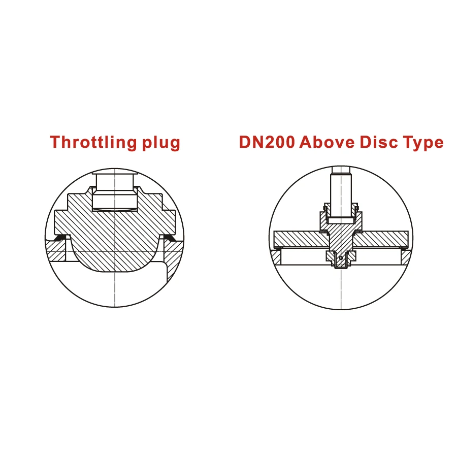
- Throttling plug: Can be discussed for service conditions requiring more controlled throttling performance.
- DN200 and above disc type: Larger-size disc configurations may be selected according to size, pressure and operating force requirements.
Testing, Installation and Operation
Testing
- Pressure testing can be provided according to EN 12266-1 and project requirements.
- The source catalog states the minimum shell strength test pressure as 1.5 x PN.
Installation
- Install in the correct flow direction according to the body mark.
- Check pipeline alignment and avoid excessive piping stress on the valve body.
Operation
- Manual handwheel operation is standard.
- Gearbox or electric actuator options may be discussed based on valve size, pressure rating and operating requirements.
- ISO 5210 flange preparation may be discussed for actuator-ready configuration.
Standards and Compliance
- Flanged connection: EN 1092-1 or project requirement.
- Butt-welded connection: EN 12627 or project requirement.
- Face-to-face dimension: EN 558-1.
- Pressure testing: EN 12266-1.
- Material certificates, inspection documentation and test reports can be discussed according to project requirements.
Frequently Asked Questions
What is the main difference between HN61 and HN60?
HN61 is a standard globe valve for shut-off and throttling service. HN60 is a bellow seal globe valve designed for applications where reduced stem leakage risk is especially important.
Can HN61 be used for throttling?
Yes. Globe valves can be selected for throttling service, but final selection should consider medium, pressure, temperature, pressure drop and operating frequency.
What information should I provide for quotation?
Please provide DN size, PN rating, body material, connection type, medium, operating temperature, quantity and any required documentation or inspection requirements.

Reviews
There are no reviews yet.